diy solar

diy solar

Shunt current off by almost 10%

Consumerbot3418

Fitting square pegs into round holes... for fun?
Joined
Jan 17, 2021
Messages
168
Location
Midwest
I picked up a B-stock second-hand Victron SmartShunt 500a, and recently integrated it into my split phase Multis. Since the Multis can only pump out 80a each (@14 volts=2240w). I wanted to install additional charging capacity, and be able to keep track of it. But now that I've completed the install, I'm surprised to see that the measured current (and power) at the shunt is substantially less than that reported by Multis--the current is off by up to 10%, and the power by 30%! In this chart, you can see the Multis charging with > 2500w, while the SmartShunt sees < 2000w.

I realize that there's a voltage drop across the DC bus, fuses, cables, and the shunt itself. That might (partially) account for the difference. But the large discrepancy in power had me concerned, questioning if bad crimps or connections may be to blame. Those 500w must be going somewhere, right?

So, at a steady 160 amps (as indicated by ve.bus/Multis, 155 amps on my clamp meter), I measured voltage drop from the battery bus bar to the inverter cables, and came up with a total of about 120mV, including fuses in the Lynx, main fuse, 2m of 4/0 cables, and lugs between. On my 12v system, that might account for about 20w lost to heat. Sure doesn't explain why 500w+ are missing!
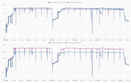
Screenshot 2023-04-18 at 1.22.23 PM.png

At this point, my best guess is that I have some combination of:
  • Multis over-reporting charge current/power
  • SmartShunt under-reporting current and voltage
  • bad crimp(s)
  • bad connection(s)
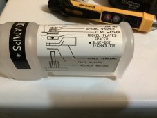
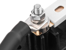
The Spartan 500a ANL fuse is getting pretty warm (over 100ºF) at just 155a. It accounts for almost a third of the voltage drop. In hindsight, I wish I'd opted for a class T fuse/holder! I'm not 100% sure what the correct hardware order is on that post. The product marketing image appears to show the lug on top of a washer, then a spacer, and finally the fuse itself on another washer, with just the nut and spring-washer on top of the lug:

Screenshot 2023-04-18 at 1.53.50 PM.png

Sure doesn't look right to my (admittedly) non-expert eyes. I installed it with the lug contacting the fuse directly, and with one of the larger stainless washers between the spring washer and the lug. Anyone care to chime in with some advice?

Meanwhile, if the SmartShunt current reading is off by over 5% (but only at 100+ amps), is it possibly a faulty unit? Or are my expectations too lofty?
Screenshot 2023-04-18 at 2.06.20 PM.png
 
You bought a low grade fuse holder that suggests putting SS in the current path, a huge no-no... Stainless is a horrible conductor...Never had an ounce of issues with Blue Sea fuse holders ans Blue Sea Bussman ANL fuses.. Also 10% is pretty good for a B-stock/used shunt....
 
You bought a low grade fuse holder that suggests putting SS in the current path, a huge no-no... Stainless is a horrible conductor...Never had an ounce of issues with Blue Sea fuse holders ans Blue Sea Bussman ANL fuses.. Also 10% is pretty good for a B-stock/used shunt....
I guess I thought a shunt would be one of those things that either worked right, or didn’t.

I’d seen others on this forum that had good luck with Spartan, and hoped to save a few pennies. I’m sure the Blue Seas stuff is great, just thought that it would be overkill for my non-marine purposes. I’d really like to confirm that I’ve got the hardware assembled in the right order before giving up on it entirely. Maybe I’ll slip a copper washer in the current path and see if that makes a difference…
 
I have one of those ANL fuse holders supplied to me by Battle Born Batteries. The large spacers on mine are nickel plated copper. The correct mounting order is on the cover but I should note it only works correctly if the cable lugs are the same thickness. Make sure the lugs, spacers and fuse blades are flat to each other. I have run 300 amps through mine and it does not heat up.

BC07F8F6-74BE-4FF6-BE80-92EFB319C3E2.jpeg
 
Current flows between compressed flat surfaces. You likely have about 0.05 milliohms on each surface compression interface.

Nickel plated spacer between terminal lug and fuse surface is about 2 x 0.05 milliohms for each surface of spacer, times two for each side of fuse for a total of about 0.2 milliohms. Plus some resistance for each cable lug.

Fuse is likely about 0.5 to 1 milliohm depending on temperature due to current flow so it dominates the series resistance.

At 155A, I would estimate 0.07 milliohms (cable lug), 0.1 milliohms fuse connection, 1 milliohm for fuse, 0.1 milliohm fuse connection, 0.07 cable lug. Total resistance from fuse/holder/cable lug to cable lug on other side = 1.34 milliohms. 1.34 milliohms x 155 amps = 0.21 volt drop across fuse, terminal lug barrel to terminal lug barrel. 155 amps through 1.34 milliohms generates about 33.5 watts of heating on fuse assembly. That will get fairly hot.

Throw an extra flat washer in the current compression connection path on each side of fuse and you up resistance by about 0.2 milliohms to 1.54 milliohms with 0.24 volt drop across fuse.

For 12v systems, with high current, this is the level of attention to detail you have to employ as a 12v system cannot afford much DC voltage drop.

Inverter regulates AC output voltage so the greater the DC input path voltage drop the more current the inverter draws for same AC output power. Inverter efficiency also degrades the lower the DC input voltage so it draws even more DC current. You can create a lot more DC current with just a small amount of path resistance between battery and inverter DC input on 12vdc input inverters.

For a higher wattage 12vdc inverter you should stick with using a fuse and avoid using a high amperage breaker. High amperage fuse is 0.5-1.0 milliohms series resistance, where a high amperage circuit breaker is 3-5 milliohms. High amperage breakers also get very hot under high load current so be careful of wire insulation used so it does not melt the insulation near wire connection to breaker. Stay away from cheap vinyl insulated cables as they will melt like marshmallow coating. Use high temperature capable insulation.

Have not yet added in battery bus bars and their compression connectors resistance, cable lugs connections, shunt (0.1 milliohms) and cable voltage drop.

Again, 12v system with 3 kW inverter has a lot of DC current. Have to be very careful to minimizing series resistance voltage drop between battery and inverter. Use your DVM on low mVdc scale and temperature of connection to check all connections voltage drop under high current load.

Just a single poor connection on one inverter can cause it to draw more current than other inverter with equal AC output power. loads. Cable gauge for high current 12v systems has to be based on voltage drop, not just cable heating.

Novices do not understand the difficulties of going above 150 amps of battery current and buy high power 12vdc inverters that can draw 250-300 amps of current. Good rule of thumb is no more than 1200-1500 watts per 12vdc of battery system voltage. DC voltage drop is a compounding problem. The more voltage drop, the more current inverter draws, creating even more voltage drop, creating even more current. 12vdc supply just does not have the margin to afford much voltage drop.
 
Last edited:
Current flows between compressed flat surfaces. You likely have about 0.05 milliohms on each surface compression interface.

Nickel plated spacer between terminal lug and fuse surface is about 2 x 0.05 milliohms for each surface of spacer, times two for each side of fuse for a total of about 0.2 milliohms. Plus some resistance for each cable lug.

Fuse is likely about 0.5 to 1 milliohm depending on temperature due to current flow so it dominates the series resistance.

At 155A, I would estimate 0.07 milliohms (cable lug), 0.1 milliohms fuse connection, 1 milliohm for fuse, 0.1 milliohm fuse connection, 0.07 cable lug. Total resistance from fuse/holder/cable lug to cable lug on other side = 1.34 milliohms. 1.34 milliohms x 155 amps = 0.21 volt drop across fuse, terminal lug barrel to terminal lug barrel. 155 amps through 1.34 milliohms generates about 33.5 watts of heating on fuse assembly. That will get fairly hot.

Throw an extra flat washer in the current compression connection path on each side of fuse and you up resistance by about 0.2 milliohms to 1.54 milliohms with 0.24 volt drop across fuse.
I don't claim to be an expert, but I measured (and reported) a voltage drop of 120mV@155a in my original comment. That was from the battery bus through the main fuse, its associated lugs, and the distribution bus with its fuses, and the shunt: about 60mV each on pos and neg. I just reconfirmed that measurement, and also checked across just the fuse assembly (including crimps, lugs, spacers, and fuse itself) and measured 35mV, which is a small fraction of your 210mV estimate. At 315 amps, I measured the fuse assembly voltage drop at just 85mV. It's enough to make me doubt my meter. I'll probably confirm the measurements with another.

Novices do not understand the difficulties of going above 150 amps of battery current and buy high power 12vdc inverters that can draw 250-300 amps of current. Good rule of thumb is no more than 1200-1500 watts per 12vdc of battery system voltage. DC voltage drop is a compounding problem. The more voltage drop, the more current inverter draws, creating even more voltage drop, creating even more current. 12vdc supply just does not have the margin to afford much voltage drop.
I'll confess that I had some reservations about going with a 12V nominal system, but consider building this high-amperage system a learning experience. I ran the calculations for the wire size, and gave it plenty of breathing room, but admit I didn't attempt to do the math of accounting for resistance across each mating surface, as you kindly detailed in your reply.

It looks like, in a worst-case scenario, I'll pull up to 400 amps at 10V (if running full-tilt as the battery dies), which I'm estimating would amount to a loss of 160w among the cables, shunt, fuse, and distribution bus. I might look into seeing if there's a way to limit amps drawn from the battery as the voltage droops... I'm thankful for the flat discharge curve on the LFP cells, but I'd rather not pull that much juice from them as they're depleted, anyway.
 
I have one of those ANL fuse holders supplied to me by Battle Born Batteries.

Thanks, @Q-Dog ! Your reply helped me find this page about their ANL fuse holders, which is extraordinarily helpful--they even specify torque values!

I contacted the vendor of the ANL fuse and holder, InvertersRUs, to inquire about the correct order of hardware. I referenced that Battle Born page, and they confirmed that the image showing the spring washer directly on top of the lug (and stainless washer in the current path) is wrong. They also told me the Battle Born diagram is accurate. I have a Blue Seas 500a ANL fuse coming soon--once it's installed, I'll check the voltage drop across it, and see if there's any improvement.
 
Last edited:
I don't claim to be an expert, but I measured (and reported) a voltage drop of 120mV@155a in my original comment. That was from the battery bus through the main fuse, its associated lugs, and the distribution bus with its fuses, and the shunt: about 60mV each on pos and neg. I just reconfirmed that measurement, and also checked across just the fuse assembly (including crimps, lugs, spacers, and fuse itself) and measured 35mV, which is a small fraction of your 210mV estimate. At 315 amps, I measured the fuse assembly voltage drop at just 85mV. It's enough to make me doubt my meter. I'll probably confirm the measurements with another.
Do you have a filter to remove the large 120 Hz (2x AC line frequency) created from sinewave inverter to yield true average DC voltage to DVM? Without the filter the DVM reading may not represent the correct voltage drop. All battery monitors have this filter for voltage averaging from current shunt. It is typically about a 1 Hz or lower low pass filter.

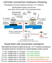
Something like the R-C filter in this diagram.
Bus bar connection testing.png
 
Do you have a filter to remove the large 120 Hz (2x AC line frequency) created from sinewave inverter to yield true average DC voltage to DVM? Without the filter the DVM reading may not represent the correct voltage drop. All battery monitors have this filter for voltage averaging from current shunt. It is typically about a 1 Hz or lower low pass filter.

Something like the R-C filter in this diagram.

I do not...

But with 155 amps flowing, I measured 14.9mV across the 500a (0.1mΩ?) shunt. So it looks like I’m within 5% of the expected reading of 15.5mV, right? I also measured across a segment of 4/0 cable. At 0.049mΩ/foot, I'd expect to see about 7.6mV drop per foot, and I was within 5% of that, too--so it looks like I'm at least in the ballpark. I tried measuring across the fuse itself, and got 23mV, so I guess it must be somewhere around 0.15mΩ.

I guess my takeaway is that I should be happy with a 35mV drop across the entire fuse assembly at 155 amps. I didn't see a specification for the resistance of the Blue Seas 500a ANL fuse that I'll be installing tomorrow, but it's nice to have a basis for comparison now, at least!
 
Last edited:
Installed the Blue Seas fuse.

The new fuse drops 17mV@155a, vs 23mV with the original Spartan Power fuse. And the entire assembly is now down to a ≈26mV drop, vs 35mV with the original fuse installed--that means that not only is the fuse itself dropping less voltage, the contact at the mating surface is improved, too. At 315a, now 60mV vs 85mV. Doesn't seem to be getting nearly as warm at the 4/0 lug, either, but that's pretty subjective, I guess.

The blades on the Blue Seas fuse appear to be twice as thick as the original (or the same thickness, folded in half), and are silver plated, while the Spartan Power fuse is shiny, and claims to be gold-plated.

In any case, I'm glad to have the ≈25% reduction in fuse holder assembly impedance. But in the big picture, it is less than a 10% drop for the system.

With the 2x 2000W Multis at a 50% load, I've calculated DC distribution loss at 0.7% (not accounting for ripple), but at full load it jumps up to 4%. I've enabled the ESS "limit inverter power" option, set to 2000W. It will surge beyond, but won't keep a sustained load beyond that target, unless I lose the AC input, in which case I'll be conserving power as much as possible, anyway!

I'm feeling pretty pleased with the system overall now, aside from the SmartShunt problem. I'm now waiting to hear back from the vendor to see what kind of resolution they offer.
 
Back
Top