@Hedges @MurphyGuy - When I lead software development projects I'm very good at breaking down a project into achievable units and iterating so that we can both show traction and successes as well as reduce risk to a big bang deliverable.
Therefore, my inclination is to do the same with this system. I'm wondering if that inclination makes sense, or if you would talk me out of it.
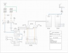
What it means to me is that I might build a small off-grid system, possibly just one SB and one SI to start, and a very under-circuited critical loads panel and a suite of AC-sockets for grid-down battery backup to get comfortable with all of the components, get it functioning, and to have some battery backup capacity soonest.
Then, in a step-wise fashion build out a larger off-grid sub-system which would eventually be grid-tied.
Risks: Would not want truly critical systems on the critical load panel, so v1 would probably just be battery backup capability.
May need to rewire later when going to grid if something not done to code.
Planned ballasted ground mount array not passing inspection.
Logical iterations could be:
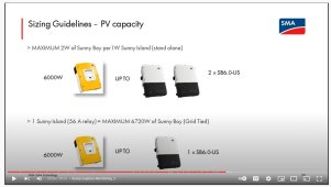
1) SB with SI w/ battery backup powered wired to suite of sockets to support critical loads via long tangle of extension cords.
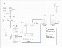
2) Add 2nd SB and 2nd SI and possibly battery with a modest set of critical loads.
3) Go through permitting process
4) Grid Tie / Rewire main panels and complete critical loads panel


")