diy solar

diy solar

Sol-Ark 15k - Surge Amps

I just flashed my 12K with the newest 6216 firmware. Punched the start button on my jointer (1.5HP) and the inverter tripped instantly. I had a clamp ammeter (Fluke 325) on the battery cables and the transient was so short that the max function didn't even see it. All I got was the 1.6A reading that was there before I headed to the shop.
 
Contact SolArk. The reportedly have fantastic support.
It would seem your load should be well within its surge capability. I wonder if the windings have a DC resistance and LRA (locked rotor amps) that is too high, greater than our estimated surge.
Please tell us how it goes.
 
Is it possible that it's one of those weird tools that only draws power during part of the sine wave? I know even Victron says not to use those with their inverters.
 
Is it possible that it's one of those weird tools that only draws power during part of the sine wave? I know even Victron says not to use those with their inverters.
it's a pretty generic induction motor. No soft-start, no speed control. Just plain vanilla motor.
 
It would be helpful to see like a picture, what size of breaker you have it attached to, and any brand information on the device?
It's a eearly1990's Chinese clone jointer (think Grizzley and the like). The motor is a generic Taiwanese 1.5HP induction motor. The nameplate claims it's a Type A motor, 3450 RPM, 9A @ 230V. 20A breaker.
 
It's a eearly1990's Chinese clone jointer (think Grizzley and the like). The motor is a generic Taiwanese 1.5HP induction motor. The nameplate claims it's a Type A motor, 3450 RPM, 9A @ 230V. 20A breaker.
9A equates to 2.78HP is it capacitive start?
 
Riddle me this, how is that you have a 20A 220V AC breaker between your jointer, your Sol-Ark can supply 37.5A 240V, and when you fire up your jointer it trips the Sol-Ark, but not the choke point of your 20A breaker? There must be something odd about the way that device either consumes energy or perhaps the Sol-Ark isn't meeting its designed specification of 37.5A off-grip supply. Is it possible that you're pulling more amps on one of the lines, for example, that 37.5 is shared between both phases, so theoretically each phase only supplies about 18.75 amps, so maybe you're pulling a large load on one phase, it's higher than the Sol-Ark maximum of 18.75 per phase but lower than the 20A of the breaker??
 
Riddle me this, how is that you have a 20A 220V AC breaker between your jointer, your Sol-Ark can supply 37.5A 240V, and when you fire up your jointer it trips the Sol-Ark, but not the choke point of your 20A breaker? There must be something odd about the way that device either consumes energy or perhaps the Sol-Ark isn't meeting its designed specification of 37.5A off-grip supply. Is it possible that you're pulling more amps on one of the lines, for example, that 37.5 is shared between both phases, so theoretically each phase only supplies about 18.75 amps, so maybe you're pulling a large load on one phase, it's higher than the Sol-Ark maximum of 18.75 per phase but lower than the 20A of the breaker??
Start up surge
 
how is that you have a 20A 220V AC breaker between your jointer, your Sol-Ark can supply 37.5A 240V, and when you fire up your jointer it trips the Sol-Ark, but not the choke point of your 20A breaker?

That would be because fast-trip of a 20A breaker occurs at about 100A, and slow-trip of a thermal-magnetic 20A breaker at 40A probably takes 5 or 10 minutes.

If this is a 1990's motor, could have a bad capacitor and could have cooked windings.
 
Could still have weak starting torque, and takes advantage of more "Oomph" from those.
My compressor was getting to have trouble restarting vs. cold start, then it wouldn't.

Talk to SolArk. They may be able to tune it more aggressively.
Being a high-frequency inverter, expect it to be limited by boost converter and PV input, but HV caps charged to enough voltage could give headroom.
Wish we had waveforms to see what it does.

Here's what I get to see, in this case 80A inrush peak at 120/208Y from my Sunny Island into a transformer:


Per spec that should be able to do 33 kW surge for 3 seconds, but battery is undersize and worn out, so only about 40 Ah 48V available. As a SWAG, I might expect 15 kVA from it. I think the initial cycle waveform is within that (not a sine wave, so I'd have to crunch numbers further.)
 
Could still have weak starting torque, and takes advantage of more "Oomph" from those.
The 3HP bandsaw and tablesaw motors are both brand new and run like a champ on generator power. Grid-tied friends with the same table saw (Sawstop) report no issues.

Talk to SolArk. They may be able to tune it more aggressively.
I get a long-distance shrug of the shoulders. I suppose I could ask again.

Being a high-frequency inverter, expect it to be limited by boost converter and PV input, but HV caps charged to enough voltage could give headroom.
Wish we had waveforms to see what it does.
The problem occurs with 4 x 200Ah battery at 100% SOC (4 x 300A 1 second surge, 4 x 120A continuous), 10kW of solar input available (but at 100% SOC nothing is being drawn) AND 15kW generator running.
As noted earlier, when the shop is isolated to the generator (by-passing the 12K), the tools run just fine.

My old Tektronix scope is analog - no recording. And there won't be much to waveform to see - the inverter shuts down in sub-second time. A meter to measure the kVA start load would be really interesting, but they're way too expensive and I don't know anyone who has one.
 
A current transformer and trigger on the scope could let you see the first couple of cycles.
Something like 100A, 333 mV is a common one. Maybe you even have a CT that came with SolArk.

I only needed the Fluke i2000 Rogowski coil for faster edges, inrush of transformers and SMPS.

It sounds like your SolArk is wimping out below specs, still don't know why.
Would be nice to know if the motors happen to have a massive surge way beyond usual.
Can you perform a 4-wire resistance test? Something like 10A DC source, and measure voltage?
 
It sounds like your SolArk is wimping out below specs, still don't know why.
Would be nice to know if the motors happen to have a massive surge way beyond usual.
As this discussion indicates, I'm certainly baffled (and sorely disappointed) at the Sol-Ark's failure to start these motors. My old Outback 3624FX inverters could start the tools and they had lower surge kVA ratings.
The jointer motor is marked as a Type A motor. If this matches the standard NEMA codes, the locked rotor kVA for a Type A motor is 3.14kVA/HP. For my 1.5HP motor that's 4.71kVA, a tiny fraction of the Sol-Ark rating.
Can you perform a 4-wire resistance test? Something like 10A DC source, and measure voltage?
not without a lot of difficulty.
 
About once a week my 3 ton heatpump seems to be locked up and is difficult to start.
A growatt 6000T could start it most of the time but my Solark 12K had no chance.
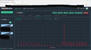
The pair of LV-SP6548 have managed it fine even with a 13kw start surge.
 

Attachments

  • SP6548 spike.jpg
    SP6548 spike.jpg
    275.7 KB · Views: 14
About once a week my 3 ton heatpump seems to be locked up and is difficult to start.
A growatt 6000T could start it most of the time but my Solark 12K had no chance.
The pair of LV-SP6548 have managed it fine even with a 13kw start surge.
Well, the LV has a full 13kW output. The Solark only has, what, 8kW inverting?
 
6.5kw each so paired up for 240v yes 13kw.
Just goes to show not all HF inverters need to be wimpy.
I have also seen 150A spike on SA monitoring. AC motors are dumb in this day and age, inverter system next time.
 
Well, the LV has a full 13kW output. The Solark only has, what, 8kW inverting?

"AC Output Power 9kW On-Grid & Off-Grid"

"Surge AC Power 10sec 16,000VA L-L (240V)
Surge AC Power 100ms 25,000VA L-L(240V)"


We expect 67A for 10 seconds.
(would be 20 HP for 10 seconds if 100% efficient)
It seems the inverter is not putting out rated current.

I said my 12K reported an F18 AC over-current fault. That was the only fault it reported in multiple shut-down events when starting any of these motors.
The manual contains this wording that I find bizarre:

F18Tz_Ac_OverCurr_FaultOverloaded the Load Output, reduce loads. Wiring Short on the AC Side can also cause this error. Overloads
can result in F15, F18, F20, or F26.

So the reported fault is AC over-current.
Motor windings when stopped are something like a short-circuit, with wire resistance and inductance due to coil and laminations providing impedance.

If LRA < 67A we expect inverter to try for a while before quitting. Maybe it is unhappy driving inductance, which shoves current back at it out of phase.

Is this with or without PV production? The architecture has inverter fed by HV capacitor bank. Battery voltage is boosted to capacitors, and PV has MPPT buck converter to charge capacitors. Maybe, boost converter current is limited (or slow to ramp up) and inverter quits when capacitor voltage drops too low. Maybe MPPT keeps capacitor bank at higher voltage. Boost converter adds to capacitor bank when voltage gets lower, and operates in reverse direction to charge battery when voltage gets higher. (Charging from AC would require additional smarts.)


Ordinarily we keep wires to a motor short. I wonder if an extension cord, adding resistance and reducing peak current, would help? Having another load already powered, so inverter is producing some current when this load is applied?

I've tried paralleling an induction motor while feeding a VFD, to see if it would reduce current distortion seen by my inverter, but it did not. Was hoping spinning mass would act as a generator to supply the peaks. In the case of a suddenly applied load, if a resistive load was already present, when voltage dropped less current would be taken by resistive load leaving more for motor.
 
Back
Top