Hopefully simple question for this crowd. I'm a long time solar owner, but everything up to now has been installed by others. (Primarily Solaredge equipment).
We moved, and I'm heading down the DIY path. The expensive stuff is all purchased and in hand, now working out the fine details:
* Sol-Ark 15k
* Nx48V LIFO4 Batteries
* 8-12 450W panels, W facing, mostly flat roof.
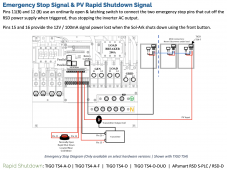
Some healthy panel shading by the house early in the morning, intending to run TS4-A-O's to compensate. Trying to understand the TIGO eco system and how it ties to the Sol-Ark.
Q1: I assume I also need a Tigo CCA to communicate to the TS4's, then be cabled RS-485 to the Sol-Ark so it can talk to the TS4's, trigger rapid shutdown, etc?
Q2: Any other questions I should be asking?
Thanks!
We moved, and I'm heading down the DIY path. The expensive stuff is all purchased and in hand, now working out the fine details:
* Sol-Ark 15k
* Nx48V LIFO4 Batteries
* 8-12 450W panels, W facing, mostly flat roof.
Some healthy panel shading by the house early in the morning, intending to run TS4-A-O's to compensate. Trying to understand the TIGO eco system and how it ties to the Sol-Ark.
Q1: I assume I also need a Tigo CCA to communicate to the TS4's, then be cabled RS-485 to the Sol-Ark so it can talk to the TS4's, trigger rapid shutdown, etc?
Q2: Any other questions I should be asking?
Thanks!