diy solar

diy solar

Sol-Ark no longer supporting gen shave

If you have a sol-ark for backup purposes, you should have enough batteries to have time to manually flip the switch. If the grid is down long enough to need the generator, you may want to stay disconnected to give the grid time to stabilize as they continue to fix it.
I am not familiar with the Generac systems but just doing some quick reading it seems like the Generac Evolution 2 Controller has sensing wires tied to the grid so that when the Grid goes down it can use a user based delay time before it turns on the Generator and outputs power. It also seems to shutdown the Generator once the grid returns and is stable.
 
I am not familiar with the Generac systems but just doing some quick reading it seems like the Generac Evolution 2 Controller has sensing wires tied to the grid so that when the Grid goes down it can use a user based delay time before it turns on the Generator and outputs power. It also seems to shutdown the Generator once the grid returns and is stable.
Generally from what I have seen and worked with (including Generac, Kohler etc.), ATSs will always have some delay switching to the gen. This comes somewhat inherently from the time it takes to start up the gen, as well as wanting to make sure the gen gets it's frequency stabilized. Also, the coils that pull the transfer switch are normally 240VAC, therefore they can't "pull" the ATS until the gen is running.

But the specific concern that was mentioned would pertain to switching back to grid, as that happens pretty quickly, and before the gen shuts down. Eg. grid power comes back on and is stabile> ATS switches back to grid> ATS controller delays 15s-5min (depending on controller)> gen shuts down. The benefit (normally, when there is no inverter involved...) is that you will only see a slight blink in the lights as it transfers back to grid. The drawback is motors that are running can see phase angle shift, causing (probably) amp spikes within the windings??? I'm not an expert on that. And also of course if there is an inverter connected and charging it could cause a possible overload on the inverter and/or stress the transfer switch in the inverter when/if it disconnects under load. Most premium inverter would probably notice the flicker and disconnect, but you could very well still have some arcing in the contacts of the inverter transfer switch.

I do believe though, that some of the newer transfer switches would be smart enough to wait to transfer until the phases are synchronized. Especially the Kohler ATSs, as the Kohlers actually have a parallel kit available that will get 2 units to automatically synchronize and share the load.

That's a bit of a bunny trail though. 🤪 Sorry, that's how I tend to end up going on discussions. LOL
 
I got the following response from Sol-Ark this morning.

So apparently this feature has been in and out of availability due to software bugs. Supposedly, the feature currently still exists in the PowerView settings. I would recommend checking back on that feature once we make the change over to MySolArk.
 
I am not familiar with the Generac systems but just doing some quick reading it seems like the Generac Evolution 2 Controller has sensing wires tied to the grid so that when the Grid goes down it can use a user based delay time before it turns on the Generator and outputs power. It also seems to shutdown the Generator once the grid returns and is stable.
That you definitely do not want to CONTROL your generator. As you state: "user based delay time before it turns on the Generator and outputs power.".

If you have solar and batteries, you want the Generator to be controlled by the Inverter, not the ATS. The ATS turns ON the generator when grid goes down, and turns it OFF when the grid comes back (allowing for delays at start/stop for stabilization, etc.). The Inverter will turn on the generator when needed to recharge the batteries. With an ATS control, the generator runs the entire time (using fuel). With Inverter control the Generator runs only when needed.

The ATS, skipping generator control, is good to isolate from the grid, and switching the grid input to the Generator. Switching back to grid needs to be done carefully to avoid: 1) Abrupt change in the AC wave form; and 2) Generator cool-down.

With a manual switch, you can disconnect the generator to allow it to cool down, and then flip a Manual Transfer Switch back to grid to allow the Inverter to re-synch to the grid before allowing power from the grid to flow through. This avoids the problem of the Inverter being synced to the Generator wave form, and then abruptly seeing the Grid wave form. Although, the switch itself could be slow enough to cause an isolation from the grid input (if the inverter is capable of isolation).
 
But any of these transfers is going to cause the Sol-Ark to disconnect from the Gird Input for several minutes anyway. If my Grid Voltage has even the slightest issue my 12K drops it and goes on PV or Batteries.
 
Good to know this. I have a pair of Schneider XW Pros with 9000 Watts of PV that is AC coupled. I only have 3 batteries at 100 amps each. Normally, I am grid tied, but I still worry about the ability of the system to handle all this PV when off-grid. I have come up with a scheme for PV Shedding when SOC is high. I plan to use the relay outputs to drive the logic for now. Maybe I will come up with something better eventually.
You need to have large enough battery size to absorb maximum PV grid-tie inverter's output in case of worse case excess power and no other place to dump it for a few seconds which is approximate time delay for freq shifting PV GT inverter to cut back its PV power generation.

If battery is too small, or too fully charged, the battery voltage will quickly rise, potentially exceeding the maximum DC input voltage limit of hybrid inverter. Battery cable path resistance also causes inverter DC input to have greater input voltage then at battery. Inverter should shutdown to protect itself but better to avoid the situation.

I believe XW inverter will not allow battery to be fully charged if using AC coupling to keep a dump reserve margin, but it does not always have control over an independent additional DC coupled charge controller directly to batteries unless it is a Xantex bus-controlled charge controller.
 
A bit of speculation here.... Be advised!

Just an FYI for anyone following this thread. Today at the shop we opened up a Sol-Ark 15K (to look at the grid transfer relays) then we took a look at the CT sensors inside and the sensors on the grid input wires are actually not PCB mounted, they are just rings over the wires, with the signal wires going to a plug on the PC board. (I had seen this before, but kind of forgot about it.) The gen input CT(s), on the other hand, seem to be PCB integrated, but I could only see one on L1.... Which makes me wonder if maybe there really is only a sensor on L1 and none on L2, with the Sol-Ark estimating the L2 current. I am somewhat speculating on this, but if this is the case, then I can totally see why Sol-Ark would want to completely discontinue the gen shave option! Monitoring only a single line would never work well!

Again, I am speculating from what I saw on the PCB. Don't take this as gospel! But this is what it would appear like to me.
 
You need to have large enough battery size to absorb maximum PV grid-tie inverter's output in case of worse case excess power and no other place to dump it for a few seconds which is approximate time delay for freq shifting PV GT inverter to cut back its PV power generation.

If battery is too small, or too fully charged, the battery voltage will quickly rise, potentially exceeding the maximum DC input voltage limit of hybrid inverter. Battery cable path resistance also causes inverter DC input to have greater input voltage then at battery. Inverter should shutdown to protect itself but better to avoid the situation.

I believe XW inverter will not allow battery to be fully charged if using AC coupling to keep a dump reserve margin, but it does not always have control over an independent additional DC coupled charge controller directly to batteries unless it is a Xantex bus-controlled charge controller.
And off course when I first lose power the batteries might already be full. On paper this all works, but I figure shedding excess PV at a high SOC will help.
 
A bit of speculation here.... Be advised!

Just an FYI for anyone following this thread. Today at the shop we opened up a Sol-Ark 15K (to look at the grid transfer relays) then we took a look at the CT sensors inside and the sensors on the grid input wires are actually not PCB mounted, they are just rings over the wires, with the signal wires going to a plug on the PC board. (I had seen this before, but kind of forgot about it.) The gen input CT(s), on the other hand, seem to be PCB integrated, but I could only see one on L1.... Which makes me wonder if maybe there really is only a sensor on L1 and none on L2, with the Sol-Ark estimating the L2 current. I am somewhat speculating on this, but if this is the case, then I can totally see why Sol-Ark would want to completely discontinue the gen shave option! Monitoring only a single line would never work well!

Again, I am speculating from what I saw on the PCB. Don't take this as gospel! But this is what it would appear like to me.
If your observation is correct, they could resolve this by using external CTs on the Gen input.
 
If your observation is correct, they could resolve this by using external CTs on the Gen input.
Because a generator AC input port must not allow back fed power there is no advantage to having CT sensor outside of inverter.

For practicality, it is bit better to put gen port CT sensor internal to ensure it works properly to prevent back feed then rely on installer/user getting the external CT sensor hookup correct. It is too easy to put CT sensor over sensed wire backwards. Long, poorly dressed CT output sense wire pairs affects the measurement accuracy of phase and current. Correct phase relationship to AC voltage is critical to determine power flow direction.

Factory can better calibrate an installed given internal CT sensor then rely on separate external CT sensor with its random make tolerance accuracy.

Inverters with external CT sensor capability usually hold a reserve margin on sensed current of a few amps positive power from utility incoming power to ensure accuracy limitations of external CT sensor power flow direction and magnitude measurement does not result in some grid back feed power when zero grid export is set in inverter.
Sol-Ark already supports and recommends generator connected to the grid using external CTs. Doing the same on the Gen input wouldn't be different. AFAIK Sunsynk doesn't have any internal CT on the Gen input and they support Gen peak shaving using external CTs. Gen peak shaving is a setting in Powerview.
 
IIRC way back before the Sol-Ark 15K was available, there was a time when you could use the external CTs for gen OR grid (on the 12K). But only one, of course, not both.

If this were still an option, then it would open up the possibility of at least choosing to use the CTs on either gen or grid. Whichever makes the most sense, or is most needed for the specific application. In a "whole house backup" scenario, using a 15K with the full 200A service passing through the inverter, there is no benefit to having the external CTs hooked up on grid wires. Then, using the CTs for gen would be perfect!
 
Because a generator AC input port must not allow back fed power there is no advantage to having CT sensor outside of inverter.
This is true except for the fact that the Sol-Arks don't limit the draw from the generator. Schneider, Outback, Magnum, etc. all have either input amps or breaker size setting. This allows the inverter to dynamically control power being drawn from the gen. E.g. as loads go up, the inverter dynamically controls the charge rate to keep the amps flowing into it at the setpoint that it has been configured to, and to avoid overloading the gen.

Since the Sol-Arks no longer have gen shave option due to apparently not being able to properly "read" power flowing into the gen terminals, the external CT sensor option would be of immense value!

Your statement is true in the sense of an internal CT inside the inverter being perfectly suitable for this! The issue here seems to be a lack of a suitable internal CT.
For practicality, it is bit better to put gen port CT sensor internal to ensure it works properly to prevent back feed then rely on installer/user getting the external CT sensor hookup correct. It is too easy to put CT sensor over sensed wire backwards. Long, poorly dressed CT output sense wire pairs affects the measurement accuracy of phase and current. Correct phase relationship to AC voltage is critical to determine power flow direction.
The external CT sensors currently coming with the Sol-Arks do need to be installed correctly. But this goes for any CT sensor application that is to read bi-directional current! The bigger, reputable, name-brand AIOs such as Sol-Ark, Eg4 (18kpv), LuxPower, etc. all come with external CT sensors that are optional. The instructions for setting them up always mention that they have to be installed correctly to work right! With external CT sensors, you get additional features, at the cost of having to install the optional CTs correctly. To me this is a very small cost for the added benefits available!
Factory can better calibrate an installed given internal CT sensor then rely on separate external CT sensor with its random make tolerance accuracy.

Inverters with external CT sensor capability usually hold a reserve margin on sensed current of a few amps positive power from utility incoming power to ensure accuracy limitations of external CT sensor power flow direction and magnitude measurement does not result in some grid back feed power when zero grid export is set in inverter.
The Sol-Ark inverters have a setting to set the minimum draw from grid between 0-500 watts. Even when set to 25 or 50 watts there tends to be some short spikes of power that flow back to grid. I am sure that even clouds passing in front of the sun can affect the power flow enough to make it hard for the inverter to respond quickly enough!
 
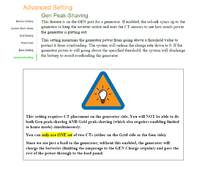
Found this in the PowerView document. The PV settings document explains things so much better than the Sol-Ark manuals.
Gen Peak Shaving.png
 

Attachments

  • PowerView-Pro-Settings-V1.0-OCT-8-2021.pdf
    1,023.3 KB · Views: 3
Found this in the PowerView document. The PV settings document explains things so much better than the Sol-Ark manuals.
Thanks for that! Although it looks like it is a 2021 document, so I don't believe that gen shave is able to use the external CT sensors anymore. I could be wrong though, so I might give it a try to see for sure.
 
Thanks for that! Although it looks like it is a 2021 document, so I don't believe that gen shave is able to use the external CT sensors anymore. I could be wrong though, so I might give it a try to see for sure.
Even if it is accessible through PowerView, almost for certain access will be gone when we migrate to MySolArk monitoring in May.
 
Back
Top