diy solar

diy solar

[SOLVED] simple schema with separate mppt charger and inverter conondrum

brandnewb

Going for serious. starting as newb
Joined
Oct 6, 2021
Messages
2,293
Location
-5m altitude from sea level
I am considering getting my feet wet with an epever mppt charger.

Their manual is conflicting in how to wire things up though.

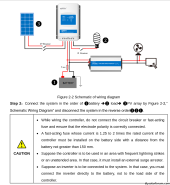
The schematic shows the inverter connected to and in between of the charger and the battery. But in the caution section underneath it is stated that when using an inverter it must be directly connected to the battery.
1694713297939.png
Can anyone please help me choose the correct way?
 
In the diagram, the inverter IS directly connected to the battery in the sense that the MPPT is not between the battery and the inverter. That's what the cautionary statement is about: they don't want you to try to power an inverter through the load ports of a solar controller.

If you're talking about a 12v battery & inverter, it's best to mount the inverter as close to the battery as possible to minimize the resistance (thus voltage drop) of the power cables since with a 12v system the currents are pretty large and you can only afford to 'lose' a small amount of voltage to your cables before the inverter triggers its low voltage shutdown and turns off. So it is still advisable to wire the inverter directly to the battery with as short and thick of wires as you can easily do.

If the inverter is large it will have a way to attach a pretty large set of cables to it. If the inverter is not that big, you would probably just use the largest wire size that will actually fit in or on the terminals of the inverter as it probably can't benefit from anything larger than that.
 
Manual might be a bit confusing but in essence you will wire to the battery from SCC with appropriate sized wire. From the battery you will wire to your inverter with large cable sized for the inverter. Many folks like to place breakers and/or fuses in between these components.

The PV charge wire and the battery to inverter cable are electrically connected forming a common DC bus.

The statement from your manual about not connecting the inverter to the SCC load terminals is because they are not designed to carry necessay inverter amperages. Most often load terminals are for an indication light or small DC load.
 
Last edited:
ok great, inverter to the battery it is then. I'll keep the topic open just a while longer in case someone has an objection to that ;)

thanks so far guys. much appreciated.
 
Back
Top