Say please, 'this slight very short duration backfeed' averaged over the 15 minutes will probably not exceed the 100 Wh that Dave21 mentioned in post #180, right?I have seen this slight very short duration backfeed whenever loads shutoff. Apparently unavoidable with a zero export grid tie inverter.


You are using an out of date browser. It may not display this or other websites correctly.
You should upgrade or use an alternative browser.
You should upgrade or use an alternative browser.
Sorotec REVO II 5,5Kw / EASUN( AXPERT/POWLAND) IGRID VE II 5,5KW
- Thread starter MikeSolarPT
- Start date
Cheap 4-life
My body is 2.63 trillion volts, .07v per cell
That’s what I’m thinkingSay please, 'this slight very short duration backfeed' averaged over the 15 minutes will probably not exceed the 100 Wh that Dave21 mentioned in post #180, right?
Dear fellow forum members, for some time now I have been the unhappy owner of 3pcs EAsun REVO 5.5kw machines with the idea of connecting them in parallel, but for more than a month I have been struggling with an unpleasant problem and I waiting more than a month for some kind of support from the engineers or someone from this brand to give an opinion on why this happens. Unfortunately, I have no answer from official EAsunpower website support except from the seller on AliExpress (Powgrow) that my complaint has been sent to the engineers, but given the inadequate questions, I am beginning to think that he is lying me. I have attached a detailed clip of that happens. It's pretty simple. I will share with you:
When the inverter is working in hybrid AC+PV mode and there is voltage supplied from the PV and the grid, a great disturbance occurs and the transformers of the site's UPSs start to hum. In the clip you will see how I make a test with a simple voltage step-down transformer that I use for an American UPS APC of 220-110V. Noise is very unpleasant and unbearable. This worries me a lot because I assume it affects all motor or compressor appliances, except that you can't use UPSs during daylight hours. In the video you will see that when I turn off the supply from the panels or from the network the problem disappears. When the inverter works with only one voltage source, there are no problems and the noise from the transformer is gone. But if it goes into hybrid mode, it becomes unbearable. I would appreciate it if there is anyone who is aware of these machines. I hope someone from the support of this brand is reading this or watching the clip, I think it is very frivolous for them not to pay attention to the emails on the official site. I am extremely disappointed with this brand. The inverter in the video works by itself without any parallels, and I'm going to parallel very soon with another one of the machines I bought.
P.S. I've read the entire thread about the model, but I didn't find a similar problem to mine, so I apologize in advance if my question is off topic.
Thanks in advance about your help and opinion about this case.
Greetings from Bulgaria.
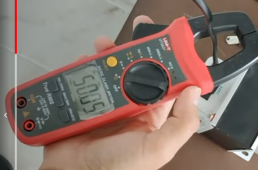
This is Hz in the networkBut this is a really great measuring instrument that can measure 50.05 V in the V~ range with the current clamp. My admiration!
")
Sorry about that I will point that in the video description
Unfortunately the problem is not related to how much load I have connected to the transformer or in parallel. All day I have a load of two water heaters, air conditioners, water pump, etc. The noise does not change in any way even if I load the transformer with the UPS. This, measuring the frequency of the current is to show that I have no differences in the input and the output, because my theory is that in order to get vibrations in the fins of the transformer, the inverter cannot give a pure sine wave the output.
You're definitely right about that. Maybe you have an oscilloscope to look at the voltage waveform directly?because my theory is that in order to get vibrations in the fins of the transformer, the inverter cannot give a pure sine wave the output.
Unfortunately, I don't have an oscilloscope, but I'm guessing I'll see a divergence in the waveforms, which doesn't solve my problem. Do you have experience and an idea if this difference can be somehow filtered when the inverter works hybridly? I was thinking of a voltage regulator, with a servo motor, but I'm sure its electronics won't handle power loads like a water pump and water heater for example. Even worse, the manufacturer does not lift a finger to give any opinion, and now I am faced with the cruel dilemma of changing the brand of inverter or waiting for some device in the circuit to succumb to these network anomal. For that, thank you very much for being here and we discussed options for several hours. I will be happy if we can find a solution and prevent others who want to get this inverter model. If it weren't for UPS MGE and APC from USA with the step-down transformer, I wouldn't even know about the disturbances in the network.
all1971si
I have measured the AC input and output, there are no differences with what the machine shows on the display. The voltage on the PV has also been measured and observed according to the characteristics of the machine. Strings of panels are grounded with surge arresters...
all1971si
I have measured the AC input and output, there are no differences with what the machine shows on the display. The voltage on the PV has also been measured and observed according to the characteristics of the machine. Strings of panels are grounded with surge arresters...
I have a spare 23kWh li-ion battery (from Think City car), which I'm planning to use as energy storage for my home. The battery consists of multiple 12S modules, each 44V nominal and about 50.7V max.
I already have a grid tied 10kWp solar plant with SMA inverter. But I plan to build completely separate system with only inverter and the battery, no solar panels!
Current energy prices here in Finland are such that off-peak might cost 0.01€/kWh and then during the day we have seen prices over 1.00€/kWh. So my plan is, fill the battery with cheap off-peak electricity and then sell that during day with huge profit. We have seen even negative prices for off-peak, they pay you to use electricity..
So I need a grid tied inverter that can charge battery from grid during night, and then discharge during day.
I have been looking at Easun Igrid 5.5kW.. It seems it perhaps could do the trick. However by default it measures grid import/export with a CT sensor and only discharges battery enough to cover your own use... I have looked into APIs found online and there doesn't seem to be a way to command it "discharge 3000W to the grid"..
Is it possible to abuse the CT sensor connection, feed some fake data to get it output any power I need? I already have SMA energy meter installed and a Raspberry Pi controlling my appliances based on the energy consumption data. So it would be trivial to add few lines of code to Raspberry, to command battery inverter "I need 1527W now".. Anyone done this? I have 40 years of experience in electronics and microcontrollers etc, so some tinkering is not an issue.
Also you can suggest a better inverter. SolaX "retrofit" models are interesting because they don't have solar (which I don't need), but current models don't seem to have configurable charger voltages anymore! They only support CAN-connected BMS now.
I already have a grid tied 10kWp solar plant with SMA inverter. But I plan to build completely separate system with only inverter and the battery, no solar panels!
Current energy prices here in Finland are such that off-peak might cost 0.01€/kWh and then during the day we have seen prices over 1.00€/kWh. So my plan is, fill the battery with cheap off-peak electricity and then sell that during day with huge profit.
We have seen even negative prices for off-peak, they pay you to use electricity..So I need a grid tied inverter that can charge battery from grid during night, and then discharge during day.
I have been looking at Easun Igrid 5.5kW.. It seems it perhaps could do the trick. However by default it measures grid import/export with a CT sensor and only discharges battery enough to cover your own use... I have looked into APIs found online and there doesn't seem to be a way to command it "discharge 3000W to the grid"..
Is it possible to abuse the CT sensor connection, feed some fake data to get it output any power I need? I already have SMA energy meter installed and a Raspberry Pi controlling my appliances based on the energy consumption data. So it would be trivial to add few lines of code to Raspberry, to command battery inverter "I need 1527W now".. Anyone done this? I have 40 years of experience in electronics and microcontrollers etc, so some tinkering is not an issue.
Also you can suggest a better inverter. SolaX "retrofit" models are interesting because they don't have solar (which I don't need), but current models don't seem to have configurable charger voltages anymore! They only support CAN-connected BMS now.
Frank in Thailand
making mistakes so you don't have to...
44v nominal is low, but should be able to work.
So all you want to do is pump and dump.
You already have a dump system, your SMA.
Winter is coming, your DC solar panels aren't going to provide that much electricity.
Thinking outside the box, why aren't you using that system?
Solar panels are DC, your battery is DC, you only need a beefy buck or boost converter to simulate being solar panel.
Your SMA won't be able to tell the difference, solar or battery DC.
It's not cherry and Banana flavour DC... ??
That should cover your own electricity usage during peak hours, and sell to the grid.
Other part is charging..
I'm positive that for a fraction of the price you are able to find 48-50v charger.
Probably the best and easiest way is eBike voltage regulator and boost converter.
They are built to endure quite a few amps, really available,and the current / voltage can be regulated.
Also not too expensive either.
For the Revo II, grid tied, they need about 300w to function.
5.5kw unit, eats up 100 - 150 watt by just being turned on.
Then being grid tied, eats an other 160w.
Solar charge, the first 100 watts is lost in translation...
So to operate one of them, grid tied,and on solar, 300 watt in Night time, 400 day time own consumption (when charging from solar)
For me, price / quality...
That 100 watt loss from solar is easy compensated with additional panel.
The 100 watt own power consumption for being inverter...
Victron and Outback don't perform much better.
The 160 watt on grid.
I have no experience with.
We live off grid.
I was surprised to read that it apparently needs this, seems kinda crazy.
I can not test, no grid
If you have 10kw inverter that can feed to the grid, why not use it to the max?
Here in Thailand we aren't even allowed to use the Revo II to connect to the grid.
Safety regulations and all.
It didn't pass any testing here
While that label usually is obtained with a large brown paper bag with high value content exchange hands during unofficial dinner ,??
ManxViking
New Member
- Joined
- Jul 22, 2021
- Messages
- 37
Hi.
I have the EASUN VE II 5.5kw hybrid inverter charger.
I have read through the extensive posts and a big thanks to everyone who has shared their troubles.
I have an 04 Bus Failure on mine and I don't even know what a BUS is, apart from the one on the roads??.
I have NO PV attached.
I am just connected to the grid for the charging and the house for discharging overnight.
Can someone tell me if there is anything I can check with a multimeter to locate which part or parts have failed, as EASUN are taking ages and I'm not going to send it back from the UK.
The unit ran for only a few days without problem.
Any advice would be gratefully received.
David
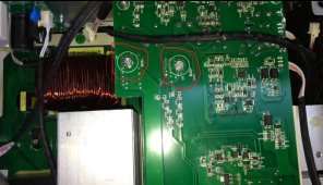
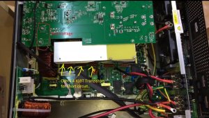
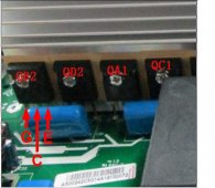
Hello, error 04 Bus Failure refers to incorrect main bus voltage charging. Check with a multimeter for a short circuit at the mppt output. If there is one, then you have a fault in the igbt transistor formatter. I recommend that the operation be performed by a licensed electrical engineer...!!!!Hi.
I have the EASUN VE II 5.5kw hybrid inverter charger.
I have read through the extensive posts and a big thanks to everyone who has shared their troubles.
I have an 04 Bus Failure on mine and I don't even know what a BUS is, apart from the one on the roads??.
I have NO PV attached.
I am just connected to the grid for the charging and the house for discharging overnight.
Can someone tell me if there is anything I can check with a multimeter to locate which part or parts have failed, as EASUN are taking ages and I'm not going to send it back from the UK.
The unit ran for only a few days without problem.
Any advice would be gratefully received.
David
There are voltages dangerous to your health in the inverter, don't forget that.
Attachments
Last edited:
Ok, Bulgarisch!
Hallo, Fehler 04 Bus Failure bezieht sich auf das falsche Laden der Hauptbusspannung. Prüfen Sie mit einem Multimeter auf einen Kurzschluss am MPPT-Ausgang. Wenn dies der Fall ist, liegt ein Fehler im Formatierer des IGBT-Transistors vor. Ich empfehle den Betrieb von Einer Elektrofachkraft durchführen zu lassen...!!!!
Im Wechselrichter liegen gesundheitsgefährdende Spannungen an, vergessen Sie das nicht.
Hello, error 04 Bus Failure refers to the incorrect charging of the main bus voltage. Check with a multimeter for a short on the mppt output. If there is, then you have a fault in the igbt transistor formatter. I recommend that the operation be carried out by a qualified electrician...!!!!
There are voltages dangerous to your health in the inverter, don't forget that.
Hello, error 04 Bus Failure refers to incorrect main bus voltage charging. Check with a multimeter for a short circuit at the mppt output. If there is one, then you have a fault in the igbt transistor formatter. I recommend that the operation be performed by a licensed electrical engineer...!!!!Hello, fault 04 Bus Failure is due to an incorrect voltage voltage on the main bus. Check with a multimeter for koso connection to exit mppt. Ako ima so, togawa imate damage in the igbt transistor formatter. Preporuchvam operation yes behold izvarshva from legal capacity electrician...!!!!
In the inverter, Ima be afraid for the health and tension, do not take the tov.
Dear thagang,
My translation is not so good. Could You translate into English, please?
There are voltages dangerous to your health in the inverter, don't forget that.
If you have any questions, ask me. I work in a solar inverter repair company in Bulgaria.
ManxViking
New Member
- Joined
- Jul 22, 2021
- Messages
- 37
Thank you. If it's something I would be better not to look at, then I will find a company here in the UK to have a look at it.
Seems it might be deadly if something went wrong. Anyone know any reputable repair shops in the south west of the UK?
David
Seems it might be deadly if something went wrong. Anyone know any reputable repair shops in the south west of the UK?
David
Similar threads
- Replies
- 33
- Views
- 3K
- Replies
- 33
- Views
- 3K
- Replies
- 0
- Views
- 205
- Replies
- 3
- Views
- 415