diy solar

diy solar

SSR testing

When I eventually test the SSR dc-ac for running 120AC up to 25amps to see how hot it gets; and then use a Thermal Disc to trigger a 2nd parallel wired mechanical relay, I have this inexpensive $23 relay in mind. I have used these with different coil voltages for water pump applications, and viewed em as durable and dependable. They might be capable of being used solo, have low coil draw/ but not sure using coil to clamp contacts 24/7. I'd be more confident of durability using these for up to full 25 AMP, as a secondary kicked to ON or closed circuit when SRR get hot. I am considering the 60 amp rated dc-c SSR w Thermal Disc triggered Mechanical Relay setup as BMS control cut off of 120ac 25 amp out from my LV2424 to 120vac Circuit Breaker Box (as option to turn off inverter by turn of full all in one/ including the charger)

General Purpose Relay Rated for 25 Amps AC DPST
Normally Open Contacts, 158 mA Rated Load Current, 12 VDC Rated Load Voltage


I ordered from Allied to get faster delivery.

 
Last edited:
The turn-on inrush current for this relay is 3.8A for 130 ms. Can Chargery BMS handle this amount of current? Probably would be good to put an oscilloscope on relay coil during turn-on.
No greater than the Electro-Mech Contactor's that Chargery has offered. The Chargery Spec says 15-30V @ 3A is what is needed to power the BMS.
 
That's what the capacitor I mentioned would be for.

How big do you think that capacitor needs to be to supply 1.7 J?

Perhaps 23 mF?
That's a huge capacitor!

So much simpler to use a transistor to apply the necessary power. Apply a 20 mS pulse to the base of the transistor and there should be any issues.
 
No greater than the Electro-Mech Contactor's that Chargery has offered. The Chargery Spec says 15-30V @ 3A is what is needed to power the BMS.
I went and looked this up in the Chargery BMS8T v4.0 manual (that mention you and this forum by name) , and found this in Frequent Questions section: " Confirm relay coil current requirement, it must not be over 1A for each relay or that the total
current with two relays won't be over 2.6A " ... earlier in manual, I see a small board that looks like option for in between BMS relay control out to big n small relay options. It was unclear to me, if that was separate card pictured was an option for bigger relay current, or internal part of BMS which I doubt. I did not see plug for external power on card picture/ but saw off on switch ? ... further into that manual, I got spec for the bigger Chargery supplied orange relay: 12V 600A relay, coil current is 1.3A at 12V drive voltage. ... just wondering out loud. ... and bet "turn-on inrush current for this relay is 3.8A for 130 ms" (not sure of accuracy) would work. / while just ... wondering out loud here.
 
  • Like
Reactions: Cal
How big do you think that capacitor needs to be to supply 1.7 J?

Perhaps 23 mF?
That's a huge capacitor!

So much simpler to use a transistor to apply the necessary power. Apply a 20 mS pulse to the base of the transistor and there should be any issues.

A simple 1F 12V supercap. The reason to not rely on a transistor is so that in the case the 12V drops for whatever reason in a catastrophic event it will still have power to turn off the relay.
 
A simple 1F 12V supercap. The reason to not rely on a transistor is so that in the case the 12V drops for whatever reason in a catastrophic event it will still have power to turn off the relay.

I wouldn't call that simple. You would need at least a 15V capacitor. You will see your catastrophic failure with your 12V cap. What happens when the cap isn't fully charged yet and the signal comes to switch relay states?

Use a $25 capacitor with iffy results when a 50 cents transistor will do the job?
 
No reason you can't do both, and add a monitoring circuit not to turn on the relay before the cap is charged. I just think it's a problem that the battery disconnect relay can keep the battery connected when the battery that it is supposed to protect is responsible to have the power available to turn it back off in order to disconnect.
 
No reason you can't do both, and add a monitoring circuit not to turn on the relay before the cap is charged. I just think it's a problem that the battery disconnect relay can keep the battery connected when the battery that it is supposed to protect is responsible to have the power available to turn it back off in order to disconnect.
Sure, you can do both. But highly likely the super cap won't work alone, even with the now added complexity. BMS low voltage disconnect is at 10.0V. There won't be enough energy in the cap for a 8V signal to trip the relay when the cap is at 10V. Will you guarantee it will trigger the relay?

A sound design will use a capacitor to "program" the timing pulse, but not provide the energy to trigger the relay directly. That should be left for a transistor or mosfet.

Cal
 
Sure, you can do both. But highly likely the super cap won't work alone, even with the now added complexity. BMS low voltage disconnect is at 10.0V. There won't be enough energy in the cap for a 8V signal to trip the relay when the cap is at 10V. Will you guarantee it will trigger the relay?

You would only use the cap to give the pulse to the relay to disconnect - it'll remain charged at 12V. A supercap self-discharge rate from 100% to 50% is 30 to 40 days. If your battery is at 10V and needs to be disconnected, will you guarantee it still has enough power to provide that to the relay (or that it indeed can still provide any power since it might have gone catastrophically wrong)?
 
Can we get this thread back to SSR testing and results. You guys have moved this way off topic. Even if it is useful info. Maybe you can start another thread.

Personally I don't want a complicated solution. The whole goal was one or 2 low draw SSR to use for HVD and LVD. This may not be possible but at least we will know what does or does not work.
 
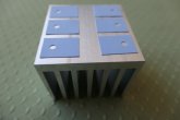
Back on track. Here's the start of my DIY high side switch. Pictured are the sil pads for the TO220 mosfets (which will take a while to arrive). 6 mosfets will fit on the 2x2" heatsink. That should get the on resistance down to 3 mOhm. The switch should easily conduct 20A.

Power dissipated = I^2 * R = 20A^2 * 0.003 ohms = 1.2 W
The heatsink might be good for 5W (40A).

The fets will be secured with a M3 screw. Got a M3 tap on order to cut threads into the heatsink.

Heatsink.jpg
 
i bought this from amazon. it run warm without load. i didn't know what is the start current for that.
Not quite an SSR, but option. If it warms up without a load, likely using some watts at trip coil. maybe you can find spec to know, or measure for amp draw. Re: Testing SSR ideas: I just found my Killawatt meter. Got too much stuff spread out here; and re-organizing my house and storage area, aiming to get to past old spring clean up project put off for too long/ to have an organized work area. My 8 x 280 Ah LifePO4s are due tomorrow. ... So SSR testing on my end will come soon, for an SSR dc-ac set up: I run 120 vac up to 20 amp. I want record rise of temps as I use more watts/ time, with and without heat sink; then record temp drops when I turn on a parallel mechanic relay to take current run too. We will see. I think that idea has greaer potential in for the higher DC amp zones (Like 500 - 1000 amps (maybe even for Electric Vehicle use, which is an arena I have not yet studied) :+)
 
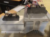
Testing an inexpensive dc-ac SSR rated for 60 Amps, without and with heat sink / with switch wired to SSR load side to imitate a potential Relay wired in parallel that could be triggered by an $12 thermostat type heat sensing disc switch.

My Results: Without Heat Sink; running 20 amps @ 116 v ac load through SSR: Temperature climbed steadily over 6 minutes from about 80F to about 200F / then when I turned switch ON @200F / to imitate a mechanical Relay placed in a parallel circuit / the Temp then dropped from 200F to 140F over 6 minutes (might have dropped more with more time? The AC Volts Drop across the load side of SSR was one volt ac / 116.5 vac input / became 115.5 vac on load side of SSR

With Heat Sink attached to SSR / 20 amps @ 116 v ac ... got slower heat rise /Temp climbed from about 80F to 115F over 9 minutes /
Then when Switch turned ON to imitate parallel mechanical type relay /Temp Dropped, but was much slower. (and my notes could have been better

My Conclusions: My Without Sink Test shows potential benefit of using a Thermal Disc (like the NO - $12 Adjustable Snap Disc Fan Control (Adjustable to Close Circuit at 140F - 180F / releases to Open circuit w 20F differential; other ranges available/ links below). to reduce heat on a SSR running much larger DC currents that would be generating more heat, with a Relay wired in parallel to bring heat down.

This Test did Not impress me as a winner to copy (though anyone could) for a dc-ac SSR running only 20 - 25 Amps, when I see using the ac -dc SSR w Heat Sink by itself topped out at about 115F @ 20 amps over 9 mins; and just saw Craig's test on higher quality AC current load SSR that did better on max temp than the cheaper on I tested.

****************
Adjustable Thermal Disc options:

The Inexpensive $18 w heat sink dc-ac SSR Relay I Tested was

Might be worth Testing this Idea out on a 200 to 500 amp DC load.
Attached picture shows one test cycle with switch imitating a relay wired in parallel.

************
Side Lesson: While using a heat gun, plus an electric induction cook top plate to produce a 20 amp load: In running 20 - 21 Amps AC through my Kill A Watt meter that is rated for 15 amps, I got a flashing display I could have paid attention to, then I burned out my Kill A Watt Meter (no big deal, already ordered another one). In the future, I will measure only up to 15 amps with those meters, and add loads I measure separately together, to get higher than 15 amp loads.
 

Attachments

  • wo.HeatSink [800x600].jpg
    wo.HeatSink [800x600].jpg
    59.5 KB · Views: 20
Last edited:
Just tested the 200 amp AC SSR ran 2500 watts through it for 30 minutes the most it heated up to was 101 degrees if that according to my heat gun. By touch it didn't even feel that warm. My shop was about 75 degrees when i started the test.
WOW, Low temp for AC current of about 20 amps. ... Seem Like Winner SSRs. Wonder How much in $ arena?
...Also wondering what the Testing large load DC current SSRs will reveal.
 
I think you missed that part the 500 amp SSR tested at 150 amps went to 170 degrees in 30 minutes
I remember that (not exact temp numbers), and think you said you thought that it got too hot ??? ... This thread is getting long enough to be a challenge to go back for easy review. Maybe at some later date, I suggest summary post most relevant test results ... info together (Later / for easy reference. I still Wonder: What kind of heat will produce on 500 amp dc-dc SSR at a 500 amp load; and if a Relay wired in parallel could bring the heat back down. and What the voltage drop will be on lad running through the SSR. ;+)
 
I remember that (not exact temp numbers), and think you said you thought that it got too hot ??? ... This thread is getting long enough to be a challenge to go back for easy review. Maybe at some later date, I suggest summary post most relevant test results ... info together (Later / for easy reference. I still Wonder: What kind of heat will produce on 500 amp dc-dc SSR at a 500 amp load; and if a Relay wired in parallel could bring the heat back down. and What the voltage drop will be on lad running through the SSR. ;+)
I think your solution has serious merritt. I think the heat dropped slowley because the heat sink was actually holding some heat so it took a bit longer to cook off. Honestly a 500 amp SSR would probably be fine 99% of the time. Especially in a 24v it 48v system
 
I guess I could cobble together a schematic. Here's the stepdown that I use.


Edit: Diagram for common port single relay

View attachment 12677

For two contactors run 12v+ through NO1/COM1 and NO2/COM2 separately to each coil+.

The parts:


This looks like my best way to wire my 5 amp SSR 3-32vdc control as OFF switch of my MPP All In One, for BMS ... low cell volt trigger or high cell volt trigger, for connection to my Chargery BMS8T. I was wondering how to use both low and high / charge and discharge control at same time on one SSR. I was considering just my BMS to discharge side to switch of All In one at low volt trigger. >>> Looks like you gave me great inexpensive relay module idea to wire one SRR to both low and high volt triggers. I will study more before wiring this up. My current understanding is the Chargery BMS8T powers the charge and discharge side to relay(s) / and release volt power at triggers. Thanks for sharing :+)
 

diy solar

diy solar
Back
Top