Capt Bill
Sailing Options
Thread got kind of long to review: Do you know if anyone consider testing this 200A rated beefy looking SSR ($30 on eBay) https://www.ebay.com/itm/Durable-SS...-4-32VDC-480VAC-200A-DC-to-AC-SL/124114069380


Thread got kind of long to review: Do you know if anyone consider testing this 200A rated beefy looking SSR ($30 on eBay) https://www.ebay.com/itm/Durable-SS...-4-32VDC-480VAC-200A-DC-to-AC-SL/124114069380
I just saw this by going backward for review here/ and this looks like a great choice for my Chargery BMS charge side control at my Solar Input to All In One ... when I configure them for Solar Charging Only (& and keep auto battery charging from grid options configured to OFF). I think I will order a couple of em. Thanks for posting those test resultsJust tested the 200 amp AC SSR ran 2500 watts through it for 30 minutes the most it heated up to was 101 degrees if that according to my heat gun. By touch it didn't even feel that warm. My shop was about 75 degrees when i started the test.
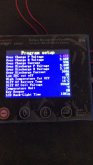
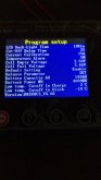
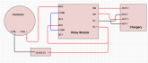
I followed the diagram and seting the relay...it overcharged the batteries to 3.9v and it still not trip. here is the program settings. please help.I guess I could cobble together a schematic. Here's the stepdown that I use.
https://www.amazon.com/gp/product/B...]https://www.amazon.com/gp/product/B00LW15F42

TE Connectivity Kilovac EV200AAANA Contactor 500A 12~24VDC Coil USA Shipper. | eBay
Find many great new & used options and get the best deals for TE Connectivity Kilovac EV200AAANA Contactor 500A 12~24VDC Coil USA Shipper. at the best online prices at eBay! Free shipping for many products!www.ebay.com
I followed the diagram and seting the relay...it overcharged the batteries to 3.9v and it still not trip. here is the program settings. please help.
same as this. i just need the battery reach 3.65 and disconnect. i tried at home and it works when charge over 3.65v. after install i changed some setting like diff of cell voltage.I'm going to give some general info first before addressing your situation. Whenever you put together a control circuit test it before leaving it unattended. For BMS systems set the max/min charge voltages down above/below the current voltage and verify that circuit is operating. Use a heat source and an ice cube to test min/max temperature cutoffs. Once your setup is verified working restore your settings and start normal operation.
Now for your specific case I would do the above testing and using a multimeter test that the Chargery relays outputs drop for the cutoff conditions. If that is working then review your wiring carefully. If the wiring is correct then you may have gotten a bad module. If you bought the two-pack it is unlikely that you received two bad modules. Try the other module and repeat the tests. If the circuit still fails looks again at your circuit wiring until you find the problem.
Also you could upload pictures of your circuit showing all the wiring and we can take a look at that.
")
I'm sure this may work but honestly you are way over my head.The thought of $55 for a Victrorn 100 Amp battery protect makes me Shudder. So I am going to try to make my own $10 design.
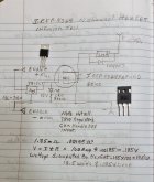
Use a 375 Amp HexFET $5.68 for the solid state switch. Here is the design and I have not tested it yet and it will need refinement.
The Driver should use a opto-coupler and FET driver. This will drive up the cost. But I still think I could make it for under $20 including the Heat Sink.
Here is the simple design. The voltage drop across the FET at 100 Amp is only .185 Volts dissipating 18.5 Watts. this is why you Need a Heat-sink.
Tell me what you think. if you need to use the device on the plus side you will need the FET driver and the opto. The RDS on for the FET is what is important for this device. see the Spec. sheet. The FET is good for 70 Volts and 195 Amps. Also you should Also use some decoupling filter caps on the regulator.
How large of a diode would be necessary and how much would that choke the current. I researched this with my own diode and found that t the hit to performance was just too much But I fully admit I am not an EE so there could be Diodes that work betterNice project
What I'd recommend:
- a diode in series with the input to prevent destroying things if connected in reverse.
- a resistor and a zener instead of the regulator (you can't use decoupling caps as it would slow down the turn on/off times too much and regulators can oscillate without them, so not a recommended configuration)
- a 12-15 V small TVS between the gate and source to protect the gate oxide layer against overvoltages if you don't chose the zener solution
- a resistor between the gate and source to force the mosfet off
- 330 Ohm seems low for the LED, especially as you don't need to drive it hard, 10 mA is plenty good enough for an indicator LED
- the 1N4007 will never handle the flyback current spike with a 100 A load. You need some big TVS and you can put it/them between the drain and source in the same direction than the mosfet body diode, no need to put it/them at the load.
How much current will you be conducting? A single fet may not be adequate. I did a similar project this spring.
High side switch
I used 6 P-channel mosfets (STP80PF55). 16 mOhms on resistance each. 10 ohm gate resistor. A BSX46 transistor turns the 6 fets on/off.
The high side switch works well. It's installed in my VW Westfalia, as a low voltage load disconnect.
How large of a diode would be necessary and how much would that choke the current. I researched this with my own diode and found that t the hit to performance was just too much But I fully admit I am not an EE so there could be Diodes that work better
I checked and at 100 A it would dissipate around 20 W worst case so that's ok given the big size package
Yes these are not Bi directional. I have devised a system where I use a DC-AC SSR after my inverter and a DC-DC SSR between panels and SCC. This has advantages and drawbacks. The advantage is the SCC always stays on and the relays are placed in the areas that flows the least amps in all cases. The disadvantage is the inverter will stay on in a lvd situation. which has never been a problem for me but could be to some. This method works exceptionally well with an all in one unit. Just add one more relay to the AC in if you are using grid power or generator for charging.See this is old thread. Did not read all pages so sorry if some my comments are redundant.
50amp with 0.1v drop is 5 watts of heating. That heatsink should be good for 15-20 watts of heat dissipation before it gets too hot to touch.
0.1v/50 amps is 2 milliohms Rs. Some of the 2 milliohm is internal connections resistance added to MOSFET Rds_ON. As mosfet gets hotter its Rs goes up 50% at about 100 degs C.
sqrt (18 watts of heating heat sink limited / 2.5 milliohms @hot temp) = 85 amps max continuous capability with a little over 0.2v of drop.
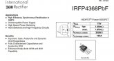
With a 75vdc rating, and from picture, probably a single HY5608W or IRFP4368PBF MOSFET which at room temp has Rds_ON of about 1.5 milliohms.
With single MOSFET this is not a bi-directional switch. If you attempt to charge battery at high current when device is OFF the reverse current will be going through MOSFET body diode and with about 1 volt reverse voltage drop could get extremely hot to point of destruction.
Not a replacement for a BMS cutout switch.
Are you using DC-AC ssr on panels or DC-DC you are posting DC-AC. I have used DC-DC ones without issue between panels and SCC 100 AMP SSR with only about 20 max amps produced by the panels.I am coming back to this thread wondering: Has anyone successfully tested a BiDirectional SSR on PV Solar Array IN to a MPPT Charge Controller, like for an easy cut off relay when BMS indicates an over charge fault: ???
Here's a dialog from another thread on this subject:
************
Hi Capt Bill. I’m very interested in your experience on this, as I seem to be trying to accomplish the same thing (controlling a ~30A/~100v Input side of my MPPT with a SSR. I was planning to use a Crydom DC200D60 for the job. Could you provide the specifics of the 120A/220vdc SSR that didn’t work for you? I’m interested in the comparing the specs to the Crydom unit I’m considering.
I should add that I’m not using a chargery BMS (I have a TinyBMS 150A), so I’m not sure if the Charger DCCs are comparable with my setup. They probably are, but I’m not crazy about employing a ‘black box’ solution that I don’t understand.
Thanks in advance.
******** my response:
I tried a couple of kind of inexpensive SSR from CoG CE company (blue lable) dc-ac rated for 220vdc./ two rated for 150Amp / and one rated for 400 amp. I tested this for my MPPT PV IN to my LV2424(s) All In Ones. / obtained these via eBay, and via Alibabaexpress. The two 150A SSRs got wasted to trash, the 400 Amp one had such I voltage drop, I took it off. for that 400 A rated one, Solar Watts Input showing on my LV2424 LCD went noticeably UP when I shorted across the SRR main current side, as briefly tested. My conclusions: First: The high Amp ratings of these small ac-dc SSR seem ridiculous to me/ Second, I kind of believe the way SSRs work, I think they do not handle the MPPT protocols going back and forth through them (but do not have specific proof other than my testing of some economical priced SSRs). Note: There may be some better quality of SSR that might work, ??? but I currently have big doubts. Let us know how you testing of that Crydom DC200D60 goes. I'll be interested.
I will add: I am successfully using some dc-ac SSRs mounted on heat sinks , on my AC circuits IN to my LV2424s that seem to work great; running 120vac up to 20 - 30 amp through dc-ac SSR rated @ 24-480vac /60 amp (obtained via Amazon; with my Alibabaexpress backups rated dc-ac SSR rated 24-480vac 120Amp. ... Hope that helps as frame of references :+)
Added Note: I have a 100 amp rated Chargery DDC Contactor on way; & think it will be a good working relay choice in that MPPT inbetween position; and I will be testing it out soon. :+)
I was using dc-dc SSR rated for up to 400 Amps at up 220vdc, and another same COGce brand 150amp rated for up to 220vdc .. Putting that in postion as a relay control switch for about 80vdc , up to 30 amps IN to my LV2424 All In One(s), just destroyed the smaller SSR, and showed a significant wattage drop at the 400 amp version. Have you ever successfully used a dc-dc SSR at that Solar IN location, maybe for BMS charge side cut off??? I was thinking/& this is just a theory with no definite proof of / that the MPPT protocal of my Solar In is in some ways bi directional. ??? I have thoughts a bi-directional SSR would do better on a DC current line with a MPPT protocols on the other side. That is why I am wondering about trying on a bi-directional SSR. I also think the SSR I tried could have just been poor quality, and I need to try one that you have tested and recommend. I know you have gotten good SSR results on main battery line; as high dc amp disconnect relay. Have you ever successful use a SSR on the Solar IN to MPPT protocol converting that dc current into both battery charging current and supply to an inverter for 120vac out ??? If so, please share that info. , including which SSR (that maybe I can get from you, Craig) for my ongoing testing ... Still fine tuning, and update tweaking for better results over here. Plus have a 2nd set of 8 280Ah cells due here soon, to up my battery bank to 560 Ah :+)Are you using DC-AC ssr on panels or DC-DC you are posting DC-AC. I have used DC-DC ones without issue between panels and SCC 100 AMP SSR with only about 20 max amps produced by the panels.
My Fuller Set Up Picture: Plus Food for Thoughts on BMS control options.Was trying to figure out why you were trying to do what you want when I realized it must be because the all-in-one has no way to have separate connections for the charging of batteries and withdraw/inverting from batteries
lol these transitor typically does 80A tops, manufacturer has their legs rated at ~120A or so.