diy solar

diy solar

Starting off my first Solar setup, got a few questions.

pacodeth

New Member
Joined
Sep 2, 2023
Messages
11
Location
USA
I will do my best to long story short this and give good-ish details. I'm wanting to setup a small array for piping power into my basement to batteries, and eventually probably to an inverter as a backup power solution when power goes out. Located in Kentucky.

So I have about 1,200 watts worth of random solar panels that I've picked up from an auction place over time at about .25 cents per watt. Basically a mixture of 200 watt panels and 100 watt panels, some solid and some flexible.

The plan is to put up 800 watts worth on top of a gazebo type structure that is in my backyard. I plan to use the MPPT that came with one of the auction solar panels I bought, a HQST MC2440N10 (12v/24v, 40 AMP, Mas Voltage of PV 100v, Max Power of PV 550w/12v 1100w/24v). For starting and testing purposes, I got a DJLBERMPW 12V 100Ah LiFePO4 Battery (Amazon Item: B09JNK13YH). Send panels to a combiner box at 24v, then to a MPPT, out to a battery bank for charging, and eventually to a Inverter.

1. First Question: I picked up a Solar Combiner box (Amazon Item: B09WY6VTGT) with 4 inputs and 10 amp fuses with 40 amp total, Max 700w at 12v, 1400W at 24v. I was planning to combine panels to make 24v inputs. So generally combining a 200 watt and 100 watt panel in Series to make 300 watts at 24v. But I'm not sure if the 10 amp fuses on this box are large enough to handle this size of input?

2. Second Question: Once I run power from the solar panels into the combiner box, what gauge wire would I need to run from the combiner box, to the MPPT which will be probably 40-50 ft away?
 
0: How do I use a hodge podge of random panels?

All panels/strings in series must have the same Imp values. If not, ALL panels in series will run at the LOWEST rated current.
All panels/strings in parallel must have highly similar Vmp values. Within 5-10% is generally decent. Note that the entire array of panels will experience about the same % of penalty, i.e., if your Vmps are 10% off, the entire 800W array would only have a 720W max potential.

1: Referring back to 0, if both 200W and 100W panels are "12V" panels, then putting them in series would force the 200W to run at the lower current of the 100W - likely about half, so the end result of their pairing would be like putting two 100W panels in series. 300W of panels would never exceed 200W of output.

2: Once you have determined your array using question 0 answer, you will have string voltage and current values. From there, you can determine the wiring needed.
 
Ah, all very good to know then! I guess I will have to re-evaluate my panel options/setup then. I woulda just bridged 200w panels together and 100w panels together but I was afraid they would run too high for the Combiner Box and MPPT I have at 400w.

I can just pump in 4x 12v things but there seemed to be a benefit to the higher wattage capabilities going 24v. So I may just have to settle with 12v and single panel hookups maybe maxing out at 700watts.
 
Here you go:

QtyBrandItemWattsVmpImp
1​
RenologyRNG-100DB-H
100​
18.9 V5.29 A
3​
RenologyRNG-175DB-H
175​
19.5 V8.98 A
4​
HQSTHQST-100D-SS
100​
20.3 V4.93 A
1​
RenologyRNG-100D-SS-2G3-US
100​
20.4 V4.91 A
1​
TopSolar
100​
18 V5.56 A
1​
ECO-WORTHYECOM100W
100​
18 V5.55 A
1​
ACOPOWERHY200-12MB
200​
20.4 V9.80 A
1​
RenologyRSP200D-G2-US
200​
22.6 V8.85 A
 
Whew...

So those are all basically "12V" panels, but dang... some compromises must be made. If you're willing to get weird with wiring, that gives you some more flexibility, e.g., 2X of the 4.9X IN PARALLEL and then in series with the ACPOWER are almost a perfect match.

Group 1:
4 of the HQST in 2S2P (40.3V, 9.86A) then in series with the ACOPOWER would result in, 60.7V and 9.80A - very little loss.

Group 2:
3S of the 175W Renology puts you at 58.5V and 8.98A

Group 3:
Series: Topsolar+Ecoworthy+100W Renology = 54.9V and 5.29A

You would then parallel all three groups yielding:

Group 1: 54.9V * 9.8A = 538W (Vmp limited by group 3)
Group 2: 54.9V * 8.98A = 493W (Vmp limited by group 3)
Group 3: 54.9V * 5.29A = 290W
Total: 1321W

vs.

1525W total

I think the only one I left out was the 200W Renology.
 
Ha sounds good to me, and thank you for all your replies!

Am I confused with the combiner box, where it has 10amp fuses, and if I were to use the above recommendations, I'd be pumping in 54.9v groups to the box?
 
Ha sounds good to me, and thank you for all your replies!

Am I confused with the combiner box, where it has 10amp fuses, and if I were to use the above recommendations, I'd be pumping in 54.9v groups to the box?
The fuses are usually rated to 150-250v so the 50v from each string isn't an issue. If you did anything I'd replace the fuses with 15a varieties as you're really pushing that 10a limit. Fortunately that's really easy to do.

The OUTPUT side however would need to be about 40a or so. 36a? That seems to be a pretty common size.
 
Wires should be sized for the current. Fuses should be 1.25X wire rating. 10A fuses are fine for group 3, but groups 1 and 2 aren't. Not enough margin. Fuses run > 80% rated will eventually blow.

15A fuses would be fine if all components in the combiner box can handle it.

Given the low current, simple MC4 branch connectors would be fine.

Since the array is complex, I'd put a single MC4 fuse in each string and an MC4 blocking diode in each string.

Linked products are examples, not recommendations.
 
Quite!

I like the arrangements above, but I'd aim for 80V as it gives better performance in low light.
Higher voltage also let you run much cheaper cable to regulator.

Fuses run > 80% rated will eventually blow.
"Quality fuses" are rated to operate up to their rated capacity.
Yes a margin is good, but a fuse operating below it's rated capacity should never blow.
 
Quite!

I like the arrangements above, but I'd aim for 80V as it gives better performance in low light.

The amount gained by 80V vs. 60V in low light conditions is negligible. It's low light. Your performance is going to be poor. However, please feel free to recommend a functional 80V arrangement for the OP.

Higher voltage also let you run much cheaper cable to regulator.

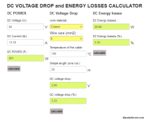
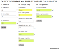
Per the OP, 50' cable run. 80V/10A is a 1.25% loss and 60V/10A is a 1.66% loss - both with 10awg cable.

"Much cheaper" 12awg would be a 1.99% voltage drop at 80V.

Something you don't mention is that the bigger the PV vs. battery difference, the less efficient the MPPT are, so any gains by going to higher voltage can be erased by MPPT efficiency losses.
 
Something you don't mention is that the bigger the PV vs. battery difference, the less efficient the MPPT are, so any gains by going to higher voltage can be erased by MPPT efficiency losses.
Does this still apply with the high vdc input rated charge controllers? My AIO inverter has a dc input rating of 450 volts and a dc system voltage of 24 volts. According to the manual the MPPT efficiency rating is up to 99 %.
 
ok, one more question. Does the battery bank need to match the input voltage from the solar panels? Or can I use the MPPT to go from 60v inputs from the solar panels, to a 12v or 24v battery bank?
 
Does this still apply with the high vdc input rated charge controllers? My AIO inverter has a dc input rating of 450 volts and a dc system voltage of 24 volts. According to the manual the MPPT efficiency rating is up to 99 %.

Yes, but to a lesser degree. A 150V MPPT is likely going to be put on a 12, 24 or 48V battery where efficiency may vary signficantly. A ~500V MPPT is optimized for high voltage/low current to start with and on a higher voltage 48V battery.

Conceptually, a 120V array on a 150V mppt charging a 12V battery will only be down maybe 4-5% from the efficiency of a ~24V array. The reduced wiring losses typically offset the reduced efficiency for long runs. However, high PV for short runs has essentially no benefit on this type of flexible controller.
 
It's low light. Your performance is going to be poor.
Yes - poor, but not negligible. I assume anyone putting together an array with such a spread of panels is on a tight budget and probably wants every Watt they can get.

a functional 80V arrangement for the OP
first - that's not how I'd do it.
I found a house about to be demolished and did a deal where I stripped 12x 270W panels from a roof. I got the rails, mounting hardware, cable and isolators - cost was an afternoons work and aud$10 per panel.

Given what we are working with:
String 1. RSP200D-G2-US + HY200-12MB + [ECOM100W // TopSolar] + [RNG-100D-SS-2G3-US // RNG-100DB-H] 800W
String 2. 4x HQST-100D-SS in series 400W
String 3. 3x RNG-175DB-H + 1x 175W panel to purchase

Giving: (S1) 800W + (S2) 400W +(S3) 700W or 1900W @80V


Something you don't mention is that the bigger the PV vs. battery difference, the less efficient the MPPT are, so any gains by going to higher voltage can be erased by MPPT efficiency losses.
Looking at a random EPEver manual, the difference is about 2% at low load dropping to 0.5% as the power increases.
1694612117649.png

Per the OP, 50' cable run. 80V/10A is a 1.25% loss and 60V/10A
For the same power, you need to allow for a higher current if you run a lower voltage
1694614801557.png1694614838844.png

Please also note this is for one wire, so you can double the losses for two wires.


That said, there are a lot of cheap PWM controllers with MPPT in their name. Beware.
Very true.
I find the easiest way to tell them apart is to look at the max input voltage spec.
If it says Max PV input 25V to charge a 12V battery, it's PWM.
It it Says Max PV input 60V to charge a 12V battery, it's MPPT.
 
The amount gained by 80V vs. 60V in low light conditions is negligible. It's low light. Your performance is going to be poor. However, please feel free to recommend a functional 80V arrangement for the OP.
Sort of wandering thru this thread, but MPPT's have a "sweet spot" for operating voltage. It's usually a range, and ususally listed in the spec. Just something to consider, efficiency also drops if you are out of that range.
 
Yes - poor, but not negligible. I assume anyone putting together an array with such a spread of panels is on a tight budget and probably wants every Watt they can get.

"Every Watt they can get" has trade-offs, and those need to be considered. Gains can be erased by losses in other areas. Designing for fringe cases is rarely the best approach.

Given what we are working with:
String 1. RSP200D-G2-US + HY200-12MB + [ECOM100W // TopSolar] + [RNG-100D-SS-2G3-US // RNG-100DB-H] 800W
String 2. 4x HQST-100D-SS in series 400W
String 3. 3x RNG-175DB-H + 1x 175W panel to purchase

Giving: (S1) 800W + (S2) 400W +(S3) 700W or 1900W @80V

Except that's not "what we are working with" as a new panel purchase is required, and it must be consistent with the others in the string. I guess budget matters above, but not now.

The array you propose is not more than 1774W as you ignored voltage and current penalties.

Looking at a random EPEver manual, the difference is about 2% at low load dropping to 0.5% as the power increases.
View attachment 167360

You provide 17 and 34V data, but you are proposing ~68V.

You're advocating high voltage for improved low power performance, but you're choosing max power performance efficiency numbers. In low light, you're going to be at the extreme left end of those curves. Conversion losses at 68V are likely to be 4% worse than at 17V, so any gains must overcome a ~4% penalty.

How often do MPPT operate at peak output? Rarely. How often do MPPT run in the range where efficiency differences are small? Maybe half the time. How often to MPPT operate at low power in low light conditions? 100% of the time.

For the same power, you need to allow for a higher current if you run a lower voltage


Please also note this is for one wire, so you can double the losses for two wires.

I didn't have an 80V array. Now I do.

54.9V/24.07A = 4.38% loss with 10awg
78V/22.76A = 4.63% loss with "much cheaper" 12awg (your argument).

In summary:
  1. "much cheaper" wire results in efficiency loss.
  2. Higher operating voltage results in greater conversion efficiency losses.
  3. Unproven claim that 80V array will outperform a 60V array in fringe cases.
I'm not seeing a strong case for potentially spending more money to get less.

Very true.
I find the easiest way to tell them apart is to look at the max input voltage spec.
If it says Max PV input 25V to charge a 12V battery, it's PWM.
It it Says Max PV input 60V to charge a 12V battery, it's MPPT.

and if they have a USB charging port.
 
Last edited:
Back
Top