Could you bond the panel, apply load, then check for current on ground between the inverter and the panel?With the inverter on and in battery/inverter mode and no loads on the output, what is the voltage from neutral to ground? If it is zero or near zero, it is almost certainly bonded. If it is not bonded you will most likely see about 60V


You are using an out of date browser. It may not display this or other websites correctly.
You should upgrade or use an alternative browser.
You should upgrade or use an alternative browser.
SunGoldPower Low Frequency Inverter UL1741
- Thread starter automatikdonn
- Start date
automatikdonn
Becoming Offgrid
There is a 2+ volt difference when on battery power. If they were bonded, the difference would be zero or near zero. (in the milli volt spectrum)
There is no specification for voltage potential differences when they are unbonded, but there surely is some reasonable expectation when they are.
I don't know how much more proof anyone would need. These inverters are not the same as others.
Also included are some pictures of the system in full operation when bonded at the main service entrance though the generator transfer switch panel.
FilterGuy
Solar Engineering Consultant - EG4 and Consumers
Ok, here is a video to show what the SGP 12KW UL units do. Neutral and Ground are surely not bonded when they are turned off and disconnected.
IDK why you would think there would be a 60v difference in potential between ground and neutral when unbonded - but when the difference is millivolts or none its clear that they are bonded. This unit does not have a ground neutral bond that I can find anywhere.
I will make another video for the unit in operation on battery power to see what it does.
This looks very similar to the Growatt 6000T DVM. In fact, they may well be rebrands of the same inverters.
The block diagram for these inverters appears to be like this:

Warning: This block diagram was developed through measurements and tests done by forum members, but has never been validated by a manufacturer. Although I believe it is accurate, I can not be 100% sure.
There are a few key things to notice about this model:
* There is no neutral in. That means the neutral output must be generated by the inverter even in passthrough mode.
* The output transformer acts as an autotransformer in passthrough mode and an isolation transformer in battery mode
* There is no dynamic bonding.
There are some important implications of the above.
1) The Neutral-ground bonding for the output must be handled externally to the inverter.
2) The NEC requires that when an autotransformer is used, the neutral generated must be tied back to the neutral of the source.
These two implications mean that there are really only two ways to set this inverter up correctly.
A) Put an NG bond on the AC out and *never* hook the input to the grid.
B) Hook the ac input to the grid and tie the output neutral back to the grid neutral creating a common neutral. (The NG bond in the main breaker box will always be the active bond)
Here is the problem with option B: Does Sungold support a common neutral? Several people have reported that setting up the Growatt with the common neutral works fine for them. However, we have had problems getting a clear statement from Growatt indicating this is a supported configuration.
You are correct. I should not have said that. Inverters with this architecture do not tend to show that large of a difference between an un-bonded output neutral and ground. They generally show a relatively small voltage between neutral and ground when unbonded. (The low-frequency inverters typically show ~60V).IDK why you would think there would be a 60v difference in potential between ground and neutral when unbonded
FilterGuy
Solar Engineering Consultant - EG4 and Consumers
I just realized we have circled back to pretty much the same posting I made much earlier in this thread.
automatikdonn
Becoming Offgrid
This looks very similar to the Growatt 6000T DVM. In fact, they may well be rebrands of the same inverters.
The block diagram for these inverters appears to be like this:
View attachment 136189
Warning: This block diagram was developed through measurements and tests done by forum members, but has never been validated by a manufacturer. Although I believe it is accurate, I can not be 100% sure.
There are a few key things to notice about this model:
* There is no neutral in. That means the neutral output must be generated by the inverter even in passthrough mode.
* The output transformer acts as an autotransformer in passthrough mode and an isolation transformer in battery mode
* There is no dynamic bonding.
There are some important implications of the above.
1) The Neutral-ground bonding for the output must be handled externally to the inverter.
2) The NEC requires that when an autotransformer is used, the neutral generated must be tied back to the neutral of the source.
These two implications mean that there are really only two ways to set this inverter up correctly.
A) Put an NG bond on the AC out and *never* hook the input to the grid.
B) Hook the ac input to the grid and tie the output neutral back to the grid neutral creating a common neutral. (The NG bond in the main breaker box will always be the active bond)
Here is the problem with option B: Does Sungold support a common neutral? Several people have reported that setting up the Growatt with the common neutral works fine for them. However, we have had problems getting a clear statement from Growatt indicating this is a supported configuration.
You are correct. I should not have said that. Inverters with this architecture do not tend to show that large of a difference between an un-bonded output neutral and ground. They generally show a relatively small voltage between neutral and ground when unbonded. (The low-frequency inverters typically show ~60V).
I am scenario B. I have not asked if they support this configuration, but I surely can and see what they say.
FilterGuy
Solar Engineering Consultant - EG4 and Consumers
See post #2 of this thread
I can tell you with the sigineer version of this hardware it specifically says never to connect grid and output neutrals. (To be clear sigineer like this one doesn't have an input neutral port).I am scenario B. I have not asked if they support this configuration, but I surely can and see what they say.
As for the question I asked earlier I just answered it myself.
I have a 12k growatt (same base hardware) and if you bond neutral in the panel and apply unbalanced load there are 0.00 amps flowing on the ground wire between the inverter and the panel. Definitely does not seem to be a neutral bond at the inverter under any circumstances. If you don't bond neutral you wind up with 0.2-0.7 volts between neutral and ground and nuisance tripping of GFCIs.
Personally I think I'm going to resolve the issue by not using grid bypass and activating a battery charger when necessary.
Why does the inverter need to generate neutral in passthrough mode if there is the grid neutral is connected to the loads panel as required by the NEC? The inverter does not need a neutral to charge the battery or supplement the AC passthrough.There are a few key things to notice about this model:
* There is no neutral in. That means the neutral output must be generated by the inverter even in passthrough mode.
FilterGuy
Solar Engineering Consultant - EG4 and Consumers
The way the system is set up with an autotransformer on the AC output, it is generating a neutral. If the inverter had a neutral in, it could switch the transformer out of the circuit completely and pass through the neutral, but that is not the way it seems to be set up.Why does the inverter need to generate neutral in passthrough mode if there is the grid neutral is connected to the loads panel as required by the NEC? The inverter does not need a neutral to charge the battery or supplement the AC passthrough.
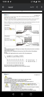
If @trig2 's point from Sigineer applies to the Sungold and my model of the inverter is correct, then what they are expecting is for an N-G bond to be placed someplace on the AC output circuit and let the output circuit operate 100% separate from the grid..... but that then violates the NEC rules. Is it possible that the inverter can not be set up in a way that is both supported and NEC-compliant? Yes. Is that the case here? It seems like it but I can't say for sure because of the lack of information from Sungold (and all the other value-priced inverter companies).Here's a page from the sigineer manual where it says to never connect input/output neutrals.
One thing I try to do is to understand what the purpose of an NEC rule is. Sometimes the purpose is obvious.... sometimes it is not. This is one I had to think about for a while. I think that the NEC recognizes that the center tap of an autotransformer will never perfectly match the center tap of the utility transformer. Therefore there will be a potential difference between them. This then creates two different neutrals in the same facility and that could lead to shock hazards and miswiring. Furthermore, by creating an N-G bond on the output like at least Siganeer seems to expect, there *will* be an undesirable current on the ground wire due to the different potentials on the neutral. Consequently, they require the two neutrals to be forced to the same potential by connecting them together.
Note: This is not the only aspect of these value-priced inverters that make it difficult to meet the NEC. The NEC requirements of PV-ground fault protection and PV Arc fault protection are very difficult to meet with these inverters.
It would be nice if the inverter had neutral input and output switch. But it seems straight forward to do similar switching outside of the inverter.The way the system is set up with an autotransformer on the AC output, it is generating a neutral. If the inverter had a neutral in, it could switch the transformer out of the circuit completely and pass through the neutral, but that is not the way it seems to be set up.
If that's really the reason then wouldn't the same risk apply to HF split-phase inverters that don't have an autotransformer? Yet the NEC rule only applies to autotransformer.One thing I try to do is to understand what the purpose of an NEC rule is. Sometimes the purpose is obvious.... sometimes it is not. This is one I had to think about for a while. I think that the NEC recognizes that the center tap of an autotransformer will never perfectly match the center tap of the utility transformer. Therefore there will be a potential difference between them. This then creates two different neutrals in the same facility and that could lead to shock hazards and miswiring. Furthermore, by creating an N-G bond on the output like at least Siganeer seems to expect, there *will* be an undesirable current on the ground wire due to the different potentials on the neutral. Consequently, they require the two neutrals to be forced to the same potential by connecting them together.
automatikdonn
Becoming Offgrid
The way the system is set up with an autotransformer on the AC output, it is generating a neutral. If the inverter had a neutral in, it could switch the transformer out of the circuit completely and pass through the neutral, but that is not the way it seems to be set up.
If @trig2 's point from Sigineer applies to the Sungold and my model of the inverter is correct, then what they are expecting is for an N-G bond to be placed someplace on the AC output circuit and let the output circuit operate 100% separate from the grid..... but that then violates the NEC rules. Is it possible that the inverter can not be set up in a way that is both supported and NEC-compliant? Yes. Is that the case here? It seems like it but I can't say for sure because of the lack of information from Sungold (and all the other value-priced inverter companies).
One thing I try to do is to understand what the purpose of an NEC rule is. Sometimes the purpose is obvious.... sometimes it is not. This is one I had to think about for a while. I think that the NEC recognizes that the center tap of an autotransformer will never perfectly match the center tap of the utility transformer. Therefore there will be a potential difference between them. This then creates two different neutrals in the same facility and that could lead to shock hazards and miswiring. Furthermore, by creating an N-G bond on the output like at least Siganeer seems to expect, there *will* be an undesirable current on the ground wire due to the different potentials on the neutral. Consequently, they require the two neutrals to be forced to the same potential by connecting them together.
Note: This is not the only aspect of these value-priced inverters that make it difficult to meet the NEC. The NEC requirements of PV-ground fault protection and PV Arc fault protection are very difficult to meet with these inverters.
You pretty well summed up how I have mine configured. They will always run in A/T mode because they are getting 240V input from my MPP 8048MAX units. I am doing things this way instead of buying an autotransformer and wiring up my own protections for it... because this unit already has most of that kinda stuff built right in.
I got a response back from SGP and it was cryptic, but pretty much they are saying the same thing Sigineer is saying - it should not be connected to grid neutral. However as you point out, there is no possible way to meet code if I don't. This configuration works well with the Pro/Tran2 panels I am using and I think I feel safe enough to move forward with the configuration at this point. One thing to change is to remove the battery connection from the SGP LF inveter - while it does make switch from grid to battery on the MPP side completely seamless - there is the possibility that it runs in battery mode and there is a potential for issues.
What does that mean for warranty support?I got a response back from SGP and it was cryptic, but pretty much they are saying the same thing Sigineer is saying - it should not be connected to grid neutral.
automatikdonn
Becoming Offgrid
LOL, like the warranty would actually be honored. I have absolutely ZERO faith their warranty. Victron, yea I think they will stand behind their product. I have just been burned so many times from overseas companies that I just don't trust them at all to honor their warranty.What does that mean for warranty support?
That is my myopic opinion
I don't think it'll run without a battery connection, would like to hear if it does.One thing to change is to remove the battery connection from the SGP LF inveter
automatikdonn
Becoming Offgrid
Oh it works just fine.I don't think it'll run without a battery connection, would like to hear if it does.

automatikdonn
Becoming Offgrid
All very good points .The way the system is set up with an autotransformer on the AC output, it is generating a neutral. If the inverter had a neutral in, it could switch the transformer out of the circuit completely and pass through the neutral, but that is not the way it seems to be set up.
If @trig2 's point from Sigineer applies to the Sungold and my model of the inverter is correct, then what they are expecting is for an N-G bond to be placed someplace on the AC output circuit and let the output circuit operate 100% separate from the grid..... but that then violates the NEC rules. Is it possible that the inverter can not be set up in a way that is both supported and NEC-compliant? Yes. Is that the case here? It seems like it but I can't say for sure because of the lack of information from Sungold (and all the other value-priced inverter companies).
One thing I try to do is to understand what the purpose of an NEC rule is. Sometimes the purpose is obvious.... sometimes it is not. This is one I had to think about for a while. I think that the NEC recognizes that the center tap of an autotransformer will never perfectly match the center tap of the utility transformer. Therefore there will be a potential difference between them. This then creates two different neutrals in the same facility and that could lead to shock hazards and miswiring. Furthermore, by creating an N-G bond on the output like at least Siganeer seems to expect, there *will* be an undesirable current on the ground wire due to the different potentials on the neutral. Consequently, they require the two neutrals to be forced to the same potential by connecting them together.
Note: This is not the only aspect of these value-priced inverters that make it difficult to meet the NEC. The NEC requirements of PV-ground fault protection and PV Arc fault protection are very difficult to meet with these inverters.
While not the most efficient, my plan is to use the inverters for function specific tasks. Knowing what I know now, I should have just bought a victron system and been done with this a long time ago.
However I would like to see what I have already bought be put to use.
In the production version of this system I have 3 MPP 8048MAX units in parallel and are connected to battery only. They supply 240v to two SGP 12kw units as an A/C input. Those are in turn connected to my Pro/Tran2 panels to provide service to the house. That takes care of getting energy from battery to the house in a way I think will be electrically safe.
On the other side of the battery are two MPP8048MAX inverters that are connected to solar and accept an input from a genset to charge in the event there is no grid and I need to charge up my battery pack. These inverters will have no A/C output in use.
I think this will all work as I intend, but to be honest I really feel like I should have just bought things piece by piece from victron. They seem to have their ducks in a row. (Electrically speaking)
It will not be very efficient in this configuration.
RCinFLA
Solar Wizard
- Joined
- Jun 21, 2020
- Messages
- 3,566
These low cost inverters do not have measurement checks for AC input neutral imbalance. Only thing they have is transformer temperature shutdown which is too slow to respond to AC input imbalance.Here's a page from the sigineer manual where it says to never connect input/output neutrals.
If you connect AC input neutral to AC output neutral, any AC input neutral imbalance will attempt to be corrected by inverter's output transformer which consumes power handling capability of output transformer. If output transformer approaches saturation, attempting to balance the grid, the inverter MOSFET's will get subjected to high current potentially blowing them out.
If you have a main breaker panel with neutral-ground bonding, and an inverter output subpanel with neutral-ground bonding, then inverter output has AC input to AC output neutral connection, even with no actual AC input neutral to AC output neutral connection, due to the common ground connections.
Assuming I have no AC inputs I run only an invert mode I bond neutral after the inverter and never mix neutrals with grid I should be okay to share the ground though right.If you have a main breaker panel with neutral-ground bonding, and an inverter output subpanel with neutral-ground bonding, then inverter output has AC input to AC output neutral connection, even with no actual AC input neutral to AC output neutral connection, due to the common ground connection.
RCinFLA
Solar Wizard
- Joined
- Jun 21, 2020
- Messages
- 3,566
Yes, if you do not connect AC input from grid.Assuming I have no AC inputs I run only an invert mode I bond neutral after the inverter and never mix neutrals with grid I should be okay to share the ground though right.
I did not come out and say it, but these inverters should not be connected to grid AC input. 99% of time grid imbalance is not a problem but when it is it can be death to inverter.
Low frequency split-phase inverters like from Xantrex, Victron, Outback, and Magnum check for AC input neutral current imbalance. It is just another grid connect criteria that must be met in order for pass-through relay to connect and stay connected to grid, just like AC input frequency and AC voltage limits criteria. If AC input neutral current imbalance gets more than a few AC amps the pass-through relay releases from grid.
You can connect a generator with no neutral connection 240vac output. Generator must not have neutral connected to ground. Most generators come default with floating neutral not connected to generator frame ground. Generator frame ground should be connected to common inverter/AC output subpanel ground. Inverter output neutral is ground bonded in subpanel.
Last edited:
Similar threads
- Replies
- 2
- Views
- 192
- Replies
- 5
- Views
- 527