idoco
New Member
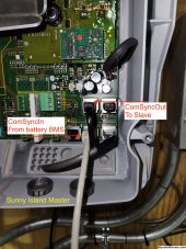
I've been running the Sunny Island-5048 x 2 operating in split phase as master/slave for the last 10+ years and just upgraded to EG4 Powerpro batteries. With a single Sunny Island master connected to the Powerpro BMS the Sunny Island and battery communicate via the CAN bus and the battery charges fine.
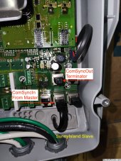
The problem I'm having is that when running the system with the slave connected to the master, the slave is throwing a CAN bus error and goes into standby mode. The master continues to work fine. The master and slave are otherwise communicating over the CAN bus as the error on slave shows up on the master log.
The Poweredge supports SMA CAN protocol and is set to use the SMA CAN protocol. The Sunny Island is set to use Li-extBMS.
Anyone with experience with the Sunny Island have any suggestions?