Did you bother to read my suggestions and look at the diagram in post #8 ?
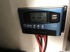
The solar controller you have is often used to control lighting with the load outputs so the lights operate during darkness. As soon as the daylight causes an Input from the solar panels the controller turns off the load.
Either use the programming option to have the load output 'on 24 hours' or connect the 12v system to the battery direct.
It's OK being new to van conversions and 12v electrics, we all started out with not much knowledge.
Your solar charge controller is not true MPPT but should give resionable performance, consider up grading in the future. It's showing 13.5 volts, so some power from the panels is charging. At this time of the year , low sun angle and possible shading, it won't be high. Refer to the setting for showing current on the display, to see the charge current.
Issues that need to be tided up.
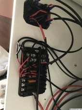
Any positive cable connected to the battery positive needs a fuse, suitable for the cable and whatever is on the end of that cable.
It seems most things are connected via the fuse distribution box. You need the appropriate fuse for each circuit, using 40 amp fuses in each location is wrong. You need a master fuse at the battery, as close as practical to the positive terminal, suggest 50A fuse and fuse holder, ( this assumes a lead acid battery)
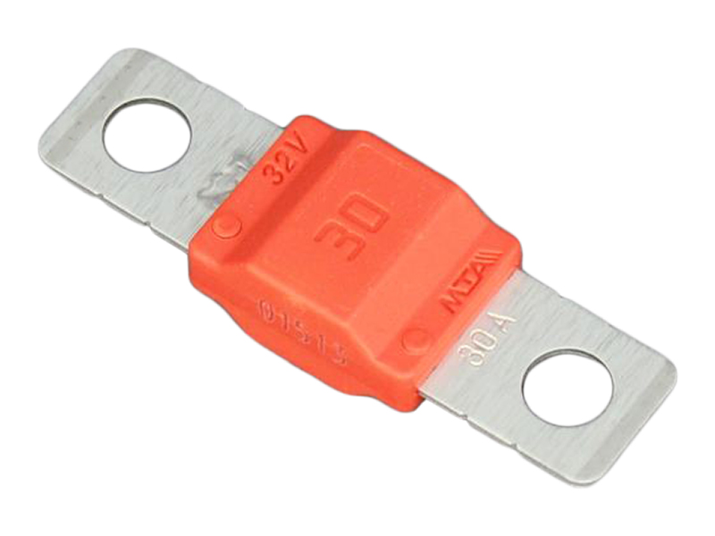
Midi link fuses used for protecting larger current circuits in automotive, marine and leisure applications. Available in current ratings from 30A to 150A.
www.12voltplanet.co.uk
The blade fuses in the fuse block will be in the range 5 to 20 amps depending on circuit.
Tidy the cables and use eye crimp connections where needed. Secure cables to relief strain on connections. Secure battery.
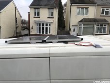
Tidy the stuff on the roof, 4 mounting brackets per panel, two per long side, at least two mounts per panel through bolted. Due to roof curvature it's easier to mount longitudinally .
The cable entry through roof does not seem fixed on a flat surface. The loose cables on the roof will 'slap' when driving, fix in place, perhaps under the panels.
Unless you already have a multimeter buy one. The best and most useful test meter for 12v systems in a meter with current clamp, example,
https://www.amazon.co.uk/MAXRIENY-Multimeter-Resistance-Continuity-ACM91/dp/B0BY3Y855J/ref=sr_1_4_sspa?crid=2IXMCB8MYUMLP&keywords=dc+clamp+meter&qid=1701532207&sprefix=dc+clamp+meter,aps,124&sr=8-4-spons&sp_csd=d2lkZ2V0TmFtZT1zcF9hdGY&th=1


") Twenty questions, anyone?
Twenty questions, anyone?