diy solar

diy solar

System Approval Requested...

Bowlegs868

New Member
Joined
Feb 8, 2022
Messages
122
Location
Trinidad and Tobago
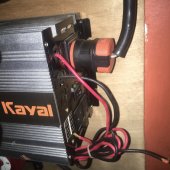
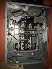
My solar installer set up my system with the output of the pure sine wave inverter feeding into a 30A breaker panel via one of the inverter's 15A AC outlets. The output of that breaker is wired into the main breaker panel of the home which is currently off-grid.

After reading a bit about grounding an off-grid system, I decided to run some checks using the continuity mode on my multimeter.

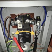
The neutral and ground on the inverter's output and the home's electrical outlets (mains) didn't beep but IT DID on the smaller 30A breaker panel that connects to the main breaker panel!

The system has worked fine*** but I'm now a little concerned. What do you guys think?
 
Photo and schematic would help.

Is your pure sine wave inverter capable of only about 15A output, or more?
30A is a common generator-input connection to a panel, but if your inverter can deliver more than 15A then should be hardwired rather than using a 15A outlet.

I would expect ground and neutral to have continuity all the way through, except for some mobile units that switch neutral.
 
Is your pure sine wave inverter capable of only about 15A output, or more?
the information on this inverter is very limited so I can't confirm and can't wait until it's time to upgrade it

I would expect ground and neutral to have continuity all the way through, except for some mobile units that switch neutral.
ohh, ok... that's where I need help

I also discovered that the panel with the 30A breaker ISN'T actually wired with a bonded neutral and ground, they're separate... there is an issue where even touching those two points (ground and neutral busbar) with my multimeter was giving off a beep! (second picture)

is this a defect in the box?
 

Attachments

  • 06C1A962-F51B-4ED7-8E8E-F25435769A14.jpeg
    06C1A962-F51B-4ED7-8E8E-F25435769A14.jpeg
    181.1 KB · Views: 18
  • 17534CFC-37C1-4631-BE98-BFC69BEDCAA3.jpeg
    17534CFC-37C1-4631-BE98-BFC69BEDCAA3.jpeg
    273.5 KB · Views: 18
  • 3AB4C65D-CD40-4D6B-A147-D7B3BEC03B39.jpeg
    3AB4C65D-CD40-4D6B-A147-D7B3BEC03B39.jpeg
    170.3 KB · Views: 18
A word of caution.

Despite code requiring a N-E bond waving grounds around transformerless inverters can be bad for their health and allow the Magic Smoke to exit if they are not specifically designed to permit this :(

Your inverter looks like one of the "cheap Chinese" units without UL / CE or any other certifications.

Does the manual have anything to say on grounding??

Do speak to the supplier about what you want to do, it may be better to leave it as an IT (floating) system. Add a 2-pole 10mA RCD (GFCI) and rely on IT being "two faults to danger".
 
Unplug the plug from inverter and check again to see if ground and neutral at panel are still connected. They may have a connection of some sort inside the inverter.


The inverter may output +60V and -60V (reversing each half cycle), which is why grounding one leg as "neutral" might be incompatible with it.

With it powered, measure voltage between the two lines (120V), and from each line to ground (see if one is 120V, other is zero, or if both are 60V.)

If output is floating you can still get the result of 60V & 60V.
What I would do next is connect a 120V incandescent lightbulb from one leg to ground and check voltages, then from other leg to ground and check voltages.
If light never lights and voltage to bulb is always zero, it is floating. If it lights dimly and is always 60V, it is midpoint grounded therefore not compatible with conventional wiring practices.
 
Your inverter looks like one of the "cheap Chinese" units without UL / CE or any other certifications.
I think it very much is...
Does the manual have anything to say on grounding??
and here's another red flag... I would love to reference a manual but, let's just say I'm still trying to find one online to this day and a physical copy didn't come with the installer
Do speak to the supplier about what you want to do, it may be better to leave it as an IT (floating) system. Add a 2-pole 10mA RCD (GFCI) and rely on IT being "two faults to danger".
the supplier is the installer so these flaws could be attributed to an error on their part or equipment defects

so would this GFCI replace the 30A breaker?
 
Unplug the plug from inverter and check again to see if ground and neutral at panel are still connected. They may have a connection of some sort inside the inverter.
well the thing about that is that the plug wasn't connected when I did the test... I made contact with the screw on the other end of the neutral busbar and there wasn't a beep but everywhere else on the busbar including the bottom screw is causing the meter to go off
With it powered, measure voltage between the two lines (120V), and from each line to ground (see if one is 120V, other is zero, or if both are 60V.)
oh ok, I'll have to try that when I get my new set of batteries
The inverter may output +60V and -60V (reversing each half cycle), which is why grounding one leg as "neutral" might be incompatible with it.

With it powered, measure voltage between the two lines (120V), and from each line to ground (see if one is 120V, other is zero, or if both are 60V.)

If output is floating you can still get the result of 60V & 60V.
What I would do next is connect a 120V incandescent lightbulb from one leg to ground and check voltages, then from other leg to ground and check voltages.
If light never lights and voltage to bulb is always zero, it is floating. If it lights dimly and is always 60V, it is midpoint grounded therefore not compatible with conventional wiring practices.
still wrapping my head around the wave of new info that I'm now finding out on grounding (sigh) so I will take my time and go through it
 
You'll likely have trouble finding a 2-pole GFCI breaker that fits in a panel and works for these voltages. For US panels they are usually 1-pole interrupting 120V or 2-pole interrupting 120/240VAC. That wouldn't provide the protection desired.

Portable GFCI are 2-pole, because they are supposed to protect even if outlet they are wired into is reversed. You can get a power strip with GFCI, plug it into inverter.

Alternate solution (if you determine this inverter doesn't tolerate grounding one end) is an isolation transformer. They cost a few bucks, even used could be as much as a cheap inverter.
 
well the thing about that is that the plug wasn't connected when I did the test... I made contact with the screw on the other end of the neutral busbar and there wasn't a beep but everywhere else on the busbar including the bottom screw is causing the meter to go off

In that case it is just lifeless wires and screws making the connection. You should be able to figure out all the connections.
 
Back
Top