diy solar

diy solar

The Big Blue Box

Zwy

Emperor Of Solar
Joined
Jan 3, 2021
Messages
6,444
Location
Timbuktu, IA
Update on the Big Blue Box from over a year ago. https://diysolarforum.com/threads/house-system-battery-box-hoffman.32305/

It's been a long process, I do not have much free time in the summer and this fall the array and EG4's I installed with some additional work done in house. A year ago in March, we cut 12 inches around the outside of the basement floor, jack hammered that out, dug down 18 inches, installed 4 inch tile to the sump pit and clean rock. then cemented it back up shut. Then I parged and waterproofed the walls, epoxied the floor. My basement is nice and dry now.

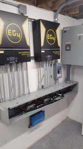
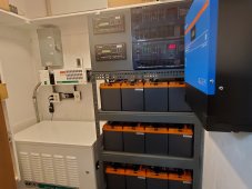
It isn't blue anymore, pics from yesterday and today. Took a little bit to get it into my basement, bolted a section of plywood on the side and slid it down the steps with the legs off. Thanks to my son for helping get it down there in the basement of my old 1905 farmhouse. Basically I put this all together in the shop, then tore it down and painted it. Now it's putting it all back together with the Batrium installed. More to come.

Yesterday

Hoffman box painted 3.jpg
Hoffman box with one door.jpg

Today
Hoffman box with breaker.jpgHoffman box shelves installed.jpg
 
Next update, getting close all wiring complete, currently installing cells.

Busbars down each side of cabinet, positive shown here. Fuse is for Batrium BMS shunt voltage sense. Main busbars are 1/4"x 1 1/4" nickel plated myself. Busbars T fuse.jpg

Next is ABB breaker with Midnite breaker to supply 48V to 24V converter for Batrium BMS power supply and ABB shunt trip which is 24V. Note the precharge resistor and push button, these only cost about $20 and some time plus wire. Breaker panel.jpg
System sits in a corner, this allowed the use of some flex conduit down to the trough for the battery cables. I need to install a plug in the bottom hole yet, keep forgetting to pick one up. Breaker panel 2.jpg

Box with cover installed. Box was purchased off ebay used for about $30. Breaker panel with cover.jpg

A few photos of finished install. EG4 6500EX complete.jpgEG4 6500EX installed.jpg

As I ordered some 304Ah B grade cells, I found the cells aren't as flat as the 280Ah so I had to modify a set of my compression fixtures for those cells. I had to tear it down and thought I would expand upon the thread here: https://diysolarforum.com/threads/compressed-pack-length.51671/

Basically it is a long threaded rod with a pvc cover made from conduit. The inwards facing nuts are set at a distance for total compression. For the 280Ah cells, it came to 1183 mm with 3 mm foam in between cells. The pvc conduit is cut slightly shorter and just reamed on the end using a step drill to allow the inward facing nut to fit inside.
Compression fixture rods 2.jpg
Compression fixture rods.jpg

A plate is installed in between the 2 nuts shown in last photo.

Pipe with plate.jpg

Next update I will show the installed battery packs and how the compression fixture works with the cabinet plus BMS install.
 

Attachments

  • EG4 6500EX complete 2.jpg
    EG4 6500EX complete 2.jpg
    97.7 KB · Views: 30
Nice. But what is that black cable tied to the top of what spears to be the positive buss-bar? I’m a sticker for consistent color codes, especially for DC.
 
Nice. But what is that black cable tied to the top of what spears to be the positive buss-bar? I’m a sticker for consistent color codes, especially for DC.
Not a cable, that is black wire loom around a red wire. I always run DC wire in a loom when possible.

Note in the panel photo, all positive wires are red with black loom.
 
please more photos! you're building basically the exact setup im planning now. i just purchased my ABB Sace S5N breaker on ebay today!

i have the same idea for the cabinet you have the ABB in. i was thinking about using the Victron Smart Shunt battery dial relay as the trigger for it? probably just have it trip if theres an over voltage/under voltage that the BMS's didnt handle or failed.

what size if the box you got from ebay?
 
24x18x6 used off ebay for $25.00, cost more to ship it. But it is a Hoffman. If you have the option, the 4 inch deep version might possibly be better. My ABB came with a standoff bracket and I had to add some extra using long 1/4" bolts and some nuts to shim it out more. You can see it in this photo.
breaker-panel-jpg.137106


For the DIN rail Midnite breaker, I just bent up a piece of DIN rail, nothing fancy about it but was cheap and easy. The only people that will ever see it are members here and myself when the cover is off. I did leave enough room to the right of the ABB if I wanted to add another ABB from another bank. I'd just move the Midnite breaker and power supply below. That would allow for a Batrium CORE on each bank controlling one ABB each so if there was a fault I'd still have battery power.
oh wow! that breaker is a lot bigger than i was thinking it was! i got the 4 pole 400 amp version so its going to be even wider.

i always forget about ebay anymore. i took a look around and found some of those Hoffman cabinets for $100 shipped. not bad! some even have random din rails and breakers in them too. pretty cool
 
I've been busy balancing cells and running Batrium balancing leads. Spent Sunday afternoon making new busbars that run from battery to T fuse. I had made some previously and even plated them but I just wasn't happy with how close a bolt was to the end plate used for compression. When working on attaching the busbars, I just used some scrap lumber to slip over the terminals to prevent shorting out cells. First photo is the slide for the end plate, this ensures the end plate doesn't not touch the backwall of the box. PVC slip.jpg

Next photo is revised busbars and the wood busbar insulators.

Busbar and wooden insulators.jpg

Next is balance leads installed, each lead is numbered with heat shrink tags. That idea came from Lithium Solar. For keeping it all tidy, I used a 1/4" wooden dowel down the center with leads plastic tied to it. Have a piece of rubber hose on the end to keep it off the cells and on the other end it goes thru a 1/4" hole in the sidewall with a short length of 1/4" hose slipped over the dowel so it couldn't be pulled back thru the hole. Balancing leads.jpg

I do have all cells in the cabinet and compressed as of last night, currently will be finishing BMS leads and busbars on the remaining cells. 304Ah on bottom shelf, 280K 3rd down and 280's top 2 shelves. The 304 and 280K's have terminals farther out, I already made negative battery cables for the battery to negative busbars made but will now have to make new cables for the bottom batteries.


Battery bank.jpg
 
Damn dude! I love how you do things!

May i ask, what is the purpose of the wire loom?
 
Damn dude! I love how you do things!

May i ask, what is the purpose of the wire loom?
Just extra protection for wires and it bundles multiple wires together neatly. I have large 100 foot plus rolls of it around here for my real job. Notice I also use loom clamps, have 1000's of those around here too especially the common sizes.

My real job involves troubleshooting and repairing of DC electrical systems. It's not the entire scope of my business, just a part of it.
 
I've been busy balancing cells and running Batrium balancing leads. Spent Sunday afternoon making new busbars that run from battery to T fuse. I had made some previously and even plated them but I just wasn't happy with how close a bolt was to the end plate used for compression. When working on attaching the busbars, I just used some scrap lumber to slip over the terminals to prevent shorting out cells. First photo is the slide for the end plate, this ensures the end plate doesn't not touch the backwall of the box. View attachment 138491

Next photo is revised busbars and the wood busbar insulators.

View attachment 138492

Next is balance leads installed, each lead is numbered with heat shrink tags. That idea came from Lithium Solar. For keeping it all tidy, I used a 1/4" wooden dowel down the center with leads plastic tied to it. Have a piece of rubber hose on the end to keep it off the cells and on the other end it goes thru a 1/4" hole in the sidewall with a short length of 1/4" hose slipped over the dowel so it couldn't be pulled back thru the hole. View attachment 138493

I do have all cells in the cabinet and compressed as of last night, currently will be finishing BMS leads and busbars on the remaining cells. 304Ah on bottom shelf, 280K 3rd down and 280's top 2 shelves. The 304 and 280K's have terminals farther out, I already made negative battery cables for the battery to negative busbars made but will now have to make new cables for the bottom batteries.


View attachment 138494
that looks so good loaded full with cell. like a battery vault!
 
  • Like
Reactions: Zwy
Update for this weekend. Spent Friday night making 2 negative cables as the 304Ah cells on lower row and 280K cells on 3rd row down have terminal spacing slightly wider. Ran balance leads on 3rd battery and did 4th battery yesterday. Finished setting up Batrium, installed temp sensors and ran some tests, then turned on inverters and setup system. Threw the 3 pole transfer switch this morning. Working excellent, batteries are fully charged and balancing. Only light flicker is when the refrigerator kicked in at startup, well pump starts fine with no flicker. Complete battery install.jpg

I showed how my transfer switch is installed and wired in this recent post. https://diysolarforum.com/threads/e...s-diagram-correct-you-asked.56258/post-732148

Installing other door later today. Very pleased with the whole project even though it took me so long to finish.
 
that looks killer! how does the Batrium work with the EG4 inverters? i read that someone was working on the communication software before?
 
Very very nice, looks well done and sturdy. With 58kWh of batts are you off grid? What kind of solar input do you have? How's the EG4's been going so far for you?

I just have 3.6kw of panels and one EG4, but hope to add some batts when funds come available.
 
Very very nice, looks well done and sturdy. With 58kWh of batts are you off grid? What kind of solar input do you have? How's the EG4's been going so far for you?

I just have 3.6kw of panels and one EG4, but hope to add some batts when funds come available.
Just 8.4Kw of panels. https://diysolarforum.com/threads/mt-solar-mount-review.51255/

I've been pulling as high as 57Kwh per day off PV. Larger loads like electric dryer are run during the day.

I would have a large battery so you can store at least 2 days minimum usage in the bank. Our minimum is about 15Kwh in a day. The other day with clouds and rain with snow coming the day after we just went to a minimum load day and used about 18Kwh per day for 2 days so I have about 3 days minimum usage storage. We had full sun yesterday and reached full charge by 2PM and that was running some electric heat while recharging.

Have the minimum PV size according to what the battery bank size is, in my case with 4 hours of good sun you can see 8 Kwh per hour, 32 Kwh in those 4 hours. The rest of the day, morning and late afternoon I see enough PV to reach full charge if it a clear day. If I only reach 80 or 90%, it seems to not matter much as I most likely will hit full charge in a day or so. Average day here with some electric heaters running until the heat pumps are installed is about 45Kwh now.
 
Very very nice, looks well done and sturdy. With 58kWh of batts are you off grid? What kind of solar input do you have? How's the EG4's been going so far for you?

I just have 3.6kw of panels and one EG4, but hope to add some batts when funds come available.
EG4's have been working well, just the light strobe/flicker once in a blue moon. I thought maybe I had a MPPT problem where it would stick at 90V input from PV as some have reported but once the sun hits the panels with a good angle in the morning, the MPPT switches on to full input.

We have been pushing these to the limits daily as I'm slightly overpaneled on the MPPT as I run a 8S string of 530W panels to each EG4 on one MPPT and not both. It maxes out the MPPT to the 4Kw daily in the middle of the day. As far as output, easily runs my well pump and the electric dryer but do need to practice some load management when large loads like the dryer are running.
 
Sounds great. Those 530W panels are a perfect fit for the 4kw/500Voc inputs. With 8 of them you really don't have to worry about the Voc max getting close to the 500V level unless it's super cold, like colder than to you have even seen. Our panels gave the same Voc as yours (49V), and I could have tried 9 panels, but that would be risky even tho we rarely get below zero here. Nine would probably work here 90% of the time, but you can't risk it.

The fact I have bifacials ought to help boost up the power beyond the rated power, even though I need to put down some white gravel or sand underneath them to help with reflecting more light onto the back cells.

I was doing some work on moving our crit loads over to the sub panel today, and noticed some LED lights do have some pulsation going on in inverter mode. But it's not consistent with even the same bulbs. I have two exact same bulbs and the pulsing is more noticeable on one than the other. Of course the incandescent bulbs don't do this, but they also use a lot more power. When I turn on the grid input all the pulsing goes away.

I notice in dim light the inverter PV input will sit at 90V, but not really go down to zero. I guess that's it's turn on/off threshold. In the early morning when it's just starting to get a bit of light, the inverter relays will click on and off incessantly until you turn it off and wait for enough light to actually get it started. Seems like it needs about 90W from the panels before it'll stay on. Of course having a battery would rectify that, but again, I don't have one yet.
 
Last edited:
  • Like
Reactions: Zwy
Very awesome battery Bank looks so commercial and Industrial you are doing some really incredible work there. Seems like I was reading something about a new software update on the eg4 inverters to correct a flickering problem you seem to be having.
 
Very awesome battery Bank looks so commercial and Industrial you are doing some really incredible work there. Seems like I was reading something about a new software update on the eg4 inverters to correct a flickering problem you seem to be having.
I have not upgraded the firmware as some had new problems after the firmware install. I prefer not being an early adopter unless desperate for a solution.

I had the scope on the circuit for the freezer all weekend waiting for the strobe and it finally came near the end of 2 days hooked up. I wanted to see if frequency changed, it doesn't and held rock solid. The flicker is caused by varying voltage, sine waves look the same as when the flicker isn't present and basically perfect. I used a short time sweep as I did not want aliasing to occur. The EG4 6500EX does not control the output voltage well with an inductive load running.
I see that's a risk I guess seems like every time something gets updated to correct a problem a lot of the time you end up with a new problem caused by the update. When I was designing my system. I had bought these two Xantrex sw5548 inverters probably 13 years ago by the time I decided to start building the system they're already outdated. I don't think I could get a permit to grid tie them. I really wanted a grid tie hybrid system badly. But then the more research I did it seemed like everyone was having problems with lots of the new hybrid inverters. A lot of them don't seem to want to start induction loads. I was excited when I saw the Solark 15K thinking that was going to be my cure. But after a lot of videos and reading unlucky stories of people buying those inverters and having trouble I decided to build two completely separate systems. A Bulletproof old xantrex backup system with all Nos equipment and it's own 10 kw of solar using victron monitoring and charging equipment. A Fronious primo 12.5 KW grid tie system with it's own 15 kw of solar. If the grid goes down the Fronious shuts off and I manual lever transfer in the Xantrex system from the power room. From the power room I can transfer in the Xantrex inverters or backup 10kw propane generator. After all my research I think this system is the best of both worlds. I'm still working on it...... it's just a backup power room at this time. The panels are all purchased and the racking is purchased. I'm hoping this summer to get all the ground mount arrays up and functional. My power room as of yesterday. I upgraded the Step up Transformer with Cooling and upgraded the power module case with Cooling. Later they will be temperature controlled. I just hung my victron RS 450 200 charge controller on Satuday. Once the power room is finished then I start in on the grid tie system mounting all that equipment outside by the meter I'm going to side tap the meter the Fronious 12.5kw is too large to backfeed the breaker box. The advantage to the side tap is I don't have to derate my breaker box.
 

Attachments

  • 20230402_212653.jpg
    20230402_212653.jpg
    196.1 KB · Views: 60
  • 20230402_162353.jpg
    20230402_162353.jpg
    168.4 KB · Views: 61
  • 20230402_162404.jpg
    20230402_162404.jpg
    105.6 KB · Views: 46
  • 20230402_172455.jpg
    20230402_172455.jpg
    188.7 KB · Views: 61
Last edited:
  • Like
Reactions: Zwy
Next update, getting close all wiring complete, currently installing cells.

Busbars down each side of cabinet, positive shown here. Fuse is for Batrium BMS shunt voltage sense. Main busbars are 1/4"x 1 1/4" nickel plated myself. View attachment 137104

Next is ABB breaker with Midnite breaker to supply 48V to 24V converter for Batrium BMS power supply and ABB shunt trip which is 24V. Note the precharge resistor and push button, these only cost about $20 and some time plus wire. View attachment 137106
System sits in a corner, this allowed the use of some flex conduit down to the trough for the battery cables. I need to install a plug in the bottom hole yet, keep forgetting to pick one up. View attachment 137107

Box with cover installed. Box was purchased off ebay used for about $30. View attachment 137108

A few photos of finished install. View attachment 137109View attachment 137111

As I ordered some 304Ah B grade cells, I found the cells aren't as flat as the 280Ah so I had to modify a set of my compression fixtures for those cells. I had to tear it down and thought I would expand upon the thread here: https://diysolarforum.com/threads/compressed-pack-length.51671/

Basically it is a long threaded rod with a pvc cover made from conduit. The inwards facing nuts are set at a distance for total compression. For the 280Ah cells, it came to 1183 mm with 3 mm foam in between cells. The pvc conduit is cut slightly shorter and just reamed on the end using a step drill to allow the inward facing nut to fit inside.
View attachment 137114
View attachment 137116

A plate is installed in between the 2 nuts shown in last photo.

View attachment 137117

Next update I will show the installed battery packs and how the compression fixture works with the cabinet plus BMS install.
I see we have similar tastes in ratchets. Good man.

Looking good too!
 

diy solar

diy solar
Back
Top