diy solar

diy solar

The Electrodacus SBMS thread (SBMS0, DSSR50, etc)

My knee-jerk reaction to using victron charge controllers with the electrodacus system is "why bother?" Once you start mixing the architectures, it is not as clear to me what the advantage is.
I did a pretty exhaustive design assessment of going "Victron" but you'll still need a BMS for cell balancing since there is no Victron product for doing that. Great if you have BB batts but if you have a DIY LFP bank, you'll stll need something like SBMS. What tipped me completely away from a Victron-centered solution is that, plus the non-MPPT assessment in my previous post. SBMS, in fact, provides all the other monitoring and charge/load control features using just one product that Victon does but requires multiple products to accomplish. As a result, it's much cheaper, takes up less space and overhead amps, and has just the features I need and nothing more (simpler to configure and maintain).

About the only thing you miss out on is VRM World which is pretty cool and the Venus GX animated displays. I'll have an LTE router in my rig so looking at how I can get Dacian's remote monitoring screens accessible from the internet. Less "wow" than Victron's displays but really there isn't any data Victron reports that SBMS doesn't as well.

And, as has been mentioned a few times above, you CAN use MPPT chargers (e.g. Victron) with SBMS0 as long as they have remote on/off switching. It just didn't make sense for me, but I can always swap out the DSSRs w MPPT(s) down the road if I come to a different conclusion after I get some time under my belt with all this.
 
I don't have experience with electrodacus but it does intrigue me.

* what kind of voltage can it handle coming off the PV array? Does it force relatively low voltage high current coming from the roof to the rest of the system?

* Where do the DSSR20 modules get installed? At the panels or with the rest of the system?

* has anyone looked at how this system would/could be used for the new NEC Fast-disconnect requirements? If the DSSR20 modules are at the panels, it might make it easy to set up a fast-disconnect. (At the disconnect, cut the signal from the controller and the + line coming down from the panels)
 
Not sure it does if you have 60-cell panels and LFP cells. This screen grab from his MPPT vs SBMS assessment convinced me that it just wasn't worth it for the minimal efficiency gain (8% if you're panels are at 5C or 41 deg F- ... 1.5% if they're at 25C or 77 deg F ... warmer than that, there's no diff). He makes many other points in the vid beyond this one, but that observation alone was enough to convince me.

View attachment 7189

I have to admit, I watched that video a while back and I was somewhat convinced of what he was saying in concept, but the details and some of the finer points are being my ability to assess (as I don't understand on a technical level how PWM and MPPT work). For instance, I know Dacian's application for his own system is stationary and unshaded. Does his analysis take into consideration potential partial shade (probably not, it seems hard to account for), is there a difference in efficiency in non-ideal conditions between MPPT and PWM?

I haven't thought too hard about PWM vs MPPT, I have always just assumed I would buy MPPT because it is the 'conventional wisdom' and because as a % of my system cost the charge controller isn't a big portion of the total system cost. The workings of charge controllers is one of the few things I haven't got around to learning about, but I suppose I should.

If its truly an across the board efficiency difference of 1.55% at 25c/77f and 0% at 45c Its definitely worth thinking hard about (and to anyone else reading this, we are talking about panel temperature, which tends to be substantially higher than ambient temperature).

I was planning to use 96 cell panels, but I'm still somewhat flexible on that.
 
Last edited:
A few comments
* I have to laugh at myself when I catch myself worrying about a small efficiency gain and not really looking at the bigger picture. I suspect that there are a lot of places where people went with the added cost of MPPT because it was 'better' but really did not need to.

I am like the poster child for this. I have spent the last few weeks obsessing over to build my own USB power delivery chargers to power my laptop, phone, etc., to gain a few percentage points of efficiency by cutting the inverter and the ac adapters out of the equation. Now this isn't completely unreasonable as that conversion can be up to 20%. But what really shows how irrational a quest it has become for me, my initial inspiration to build my own came because I didnt want to buy an off the shelve 12v version for my 24v system since the conversion down to 12v and back up to 19-20v would cost me maybe 5%. To drive that point home.. I am considering building my own laptop charger, to gain maybe 5% efficiency, on a device that uses AT MOST 54 Whrs A DAY...

I dont know what I'd do if I couldn't laugh at myself.

* For some people that 6% gain may be important.... for others it is not. Every body has different circumstances. I have installs where I would gladly give up the 6% for simplicity and cost and I have installs where I am trying to get every watt-second I can.

But yes, what sounds like small numbers all add up. And a 5% efficiency gain is no small thing in some situations.

* If I was trying to make the choice I would run the numbers for the specific equipment and costs I was choosing between. I have not gone through the chart, but since I know he was trying to prove a point, my natural skepticism doesn't allow me to take it at face value.

You should watch the video. Dacian's videos never feel like they are trying to 'push' anything or evangelize. One of the things that I've really come to like about him is his level headed, transparent, relatively impartial approach. It a rare thing nowadays but it feels like he is confident enough in his ideas and committed enough to the numbers that once he has convinced himself he does his best to explain his reasoning to others and share the data, but doesn't get preoccupied with trying to convince others and doesn't let his ego get wrapped up in his ideas. Maybe I'm reading too much into things, but on the internet where everyone (me included) is so quick to be defensive about our ideas and wanting others to agree with us I find his calm, transparent, data based approach refreshing and disarming. I mean heck, in the video where he is explaining his 100% solar off-grid system, he devotes about 15 minutes to explaining all the ways in which natural gas is a superior energy source in many contexts.
 
I don't have experience with electrodacus but it does intrigue me.

* what kind of voltage can it handle coming off the PV array? Does it force relatively low voltage high current coming from the roof to the rest of the system?

* Where do the DSSR20 modules get installed? At the panels or with the rest of the system?

I'm not positive but I believe so (maybe I'm showing my ignorance of PWM here, but isn't this the way PWM works?).

With the caveat that I know almost nothing about the DSSR20 or PWM, and that I also would like to hear more about how these units are meant to be installed/used, I have some guesses.

From the schematic and the spec sheets (post 3 of this thread or pg 3 and 4 of the manual), it looks like:
  1. each DSSR20 is optimized for 2 x 60 cell panels in parallel. (max 49V @ 20A).
  2. DSSR20's are meant to be connected in parallel up to 30 units
  3. The schematic makes it look like they get installed near the panels but this may not be accurate (but they don't look weatherproof so I suspect they aren't meant to be installed outside)
I hope someone more knowledgable than me might shed some light on here.
 
Last edited:
I'm not positive but I believe so (maybe I'm showing my ignorance of PWN here, but isn't this the way PWN works?).

In general, PWM has much lower voltage limits on the solar. However, the electrodacus equipment is enough different than other systems that I don't want to make assumptions.... that is why I asked.

  1. The schematic makes it look like they get installed near the panels but this may not be accurate (but they don't look weatherproof so I suspect they aren't meant to be installed outside)
I went through the same thought process.... and then decided to ask.

With large arrays, running lots lines down to the 'battery room' is a PITA and running a single low voltage-high amperage line can be a pain too. One of the advantages of MPPT is that they tend to accept higher voltages. This allows for higher voltage, lower amp (easier) wiring.

As with everything else, in some cases the wiring constraints will not matter and in others it might be a show-stopper.
 
I guess I am in a "Trust but verify" position.

I tend to be the same. Its a good default position to take, especially if its something important, but its also impossible to do so for everything, and that's where our judgement comes in. If I were seriously considering using the DSSR20 I would definitely run the numbers based on my actual equipment, as I'm not seriously considering that, the information I have is enough for me to place reasonable trust in his numbers (though I'm still curious how partial shade, overcast, etc effect his model).

But I highly recommend you watch the video(s) if you are of the trust but verify mindset. He spends a lot of time going over the numbers and the math and the different variables and explaining his logic and the concepts behind it, and he tends to report not just the data that supports his conclusions.

In general, PWM has much lower voltage limits on the solar. However, the electrodacus equipment is enough different than other systems that I don't want to make assumptions.... that is why I asked.


I went through the same thought process.... and then decided to ask.

A wise approach to take


With large arrays, running lots lines down to the 'battery room' is a PITA and running a single low voltage-high amperage line can be a pain too. One of the advantages of MPPT is that they tend to accept higher voltages. This allows for higher voltage, lower amp (easier) wiring.

As with everything else, in some cases the wiring constraints will not matter and in others it might be a show-stopper.

Yeah, I would like to hear more about this too. It seems like one of the bigger shortcomings in the design (considering that it's designed to handle up to 14kw of PV). 14kw @ 24v is some serious amperage and some seriously thick wires. I think this is definitely a point he needs to address.

On the other hand, its a one time expense, and a one-and-done PITA

One of the things that helps understand a lot of Dacian's design decisions is he is very concerned with cost over time. He would seems to analyze most everything through that lens (solar vs lpg heating, solar vs traditional grid tie, off grid vs on grid, battery capacity vs pv array size, alternator charging vs solar charging, mppt vs PWM, thermal storage vs battery storage). Its no the only lens he views things through, but it seems like a central consideration for him, maybe more so than for many of us.
 
Last edited:
With large arrays, running lots lines down to the 'battery room' is a PITA and running a single low voltage-high amperage line can be a pain too. One of the advantages of MPPT is that they tend to accept higher voltages. This allows for higher voltage, lower amp (easier) wiring.

As with everything else, in some cases the wiring constraints will not matter and in others it might be a show-stopper.


Yeah, I would like to hear more about this too. It seems like one of the bigger shortcomings in the design (considering that it's designed to handle up to 14kw of PV). 14kw @ 24v is some serious amperage and some seriously thick wires. I think this is definitely a point he needs to address.

random youtube commenter said:
The wirings cost ! especially when there is long distance between the solar array and the technical room, for example if you have 2000Wc with x8 250 Wc in parallel it make something like 60amps (25/35 mm2 copper wire for a low drop voltage). With some solar mppt like the MidNite CLASSIC 250 you can put 4, 5 or 6 solar panels in series in our case you will have only 15 amps at ~150VDC (4 mm2 copper wire). You can consider 0,4cts/m/mm2. Big thumbs up for you project. Regards

Dacian said:
PWM will do the same as the Solar BMS since in the bulk part there is no PWM used the PWM is used only in the constant current part of charging on Lead Acid and at that point MPPT is also useless there no gain there anymore. As for wire cost. I will have a large 7 to 9kWh array for heating and I made calculation for wire cost. The array will be relatively far about 20m (70ft) Normally with individual wires for each 8A (250W) panel you will need #10 AWG for that distance to be under 3% voltage drop. Thing is that you do not need to be at 3% and you can use #14 AWG for about 8% V drop so 5% more at full sun but average loss will be less. #14 can easily handle 8A even in a conduit with many other wires bundled. Thing is all this loss even 5% mean one additional PV panel at each 20 panels and that may be less than the extra cable. For sure less than an 5000W (250W x 20) MPPT just for that savings on cable. The #14 here in Canada can be had for about 300 to 350$/km so for each panel two wires 20m total 40m is about 14$ so not that much even for my 36 panels 9kW array at 20m total will be 36 x 14$ about 500$. For just a 3kW array what SBMS supports is about 170$ total for cable and for 2kW that MPPT in the example supported is even less so the savings can not be that large you still need cable anyway.
 
I believe that was me who posted that (maybe others elsewhere too). I was quite impressed and surprised by his line of reasoning. It was the first time I had heard anyone knowledgeable make a well reasoned argument in favor of PWN.
SBMS line, apparently, is not actually PWM (though, of course, not MPPT either). Per this reply from Dacian to someone in the comments section of the video linked in my last post:

[SBMS] is not a PWM controller as PWM is not needed for Lithium charging (it is actually detrimental). PWM is used for constant voltage charging (absorption and float) with Lead Acid that require this sort of charging. Yes, if panels match battery they can work very close to max power point so much so that it will be in average more efficient than using an MPPT. If you have the space and add more panels that will be cost equivalent with the MPPT then that is a way better financial investment.
...
A Lithium battery say a LiFePO4 that is ideal for solar as it is the most cost effective is very simple to charge and almost like a capacitor so you can connect a solar PV panel to it "directly" as solar PV panel is a constant current source and that PV panel will push current in to the battery (current will depend on amount of light) and when that LiFePO4 cell gets to 3.6V charging should immediately stop as cell is 100% charged. What a PWM will do is turn the panel ON/OFF to maintain say that 3.6V and that will have detrimental effect on a Lithium battery as the LiFePO4 is already fully charge and charging should be completely stopped. So PWM is used for constant voltage charging (absorbiton) and only constant current charging (bulk) is needed for LiFePO4. With other type of Lithium cells say LiCoO2 or NMC used in portable electronics or EV's constant voltage (absorbtion) charging can be used to get some extra storage capacity but to the detriment of battery life. In those applications the extra 15 or 20% capacity you get using constant voltage charging (absorption) is more important than battery cycle life but that is not the case with solar energy storage where cost amortization is more important than energy density. In any case LiCoO2 and NMC are not cost effective when compared to LiFePO4 and with LiFePO4 there is no extra 15 to 20% from constant voltage charging possible as this cells will be fully charged already after the constant current charge phase and there is not even 1% extra left to gain by CV charging.


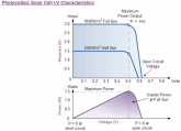
Granted, I've never been clear on the subtleties of meaning when folks refer to something being a "constant current" vs "constant voltage." Seems you can't take these at face value without context. Current from PV panels change constantly (depending on sun exposure) but their voltage doesn't (correct?) so you'd think it would be the other way 'round, though I think I get what he's saying when he refers to PV panels as "constant current" per this IV curve for a typical PV cell that I found here (Alternative Energy Tutorials):

1581548026593.png

Can someone else who understands this explain it a little better?

Hmm... there's a problem with these numbers: 239 + (239 * (25.6 / 100)) = 300.2. Well, obviously 300.2 is not 321 so that's not a 25.6 % gain... it's actually a 34.3 % gain (100 * (321 - 239) / 239). I didn't run the numbers for the other ones but I bet they are off too.
Yeah, think I have half the discrepancy figured out but wrote Dacian to confirm what I think these #s actually represent. Really want to understand the details of how SBMS vs PWM vs MPPT work. May just wind up borrowing someones MPPT charger and do a side-by-side controlled experiment (vs the DSSRs) once I set this thing up (e.g. replace that 3rd DSSR in my schematic w an MPPT and simply toggle my breakers to measure current coming in from each, running the experiment over the course of a month or so to cover wide variation in sun and temp conditions. Think I could have done that multiple times already for the amount of time I've spent trying to sort out the theory.
 
Can someone explain how the SBMS balances the cells, vs a active/passive BMS?

As for SBMS, PWM, MPPT goes. Only MPPT allows me to use 24V panels with a mobile 12V system. Higher voltage, lower current, = smaller wires.
With a DC-DC charger w/MPPT I have two ways to charge my batteries and if I'm already driving, the alternator charging is free energy.
 
As for SBMS, PWM, MPPT goes. Only MPPT allows me to use 24V panels with a mobile 12V system. Higher voltage, lower current, = smaller wires.

Well, more precisely MPPT allows you to use '24v' panels efficiently with a 12v system battery. To take full advantage of "higher voltage, lower current = smaller wires" running a 24v system and stepping down to 12v where necessary would be ideal. Alternator charging is still possible Victron and Sterling both make high quality DC-DC chargers that can do 12v to 24v (and no more difficult or expensive than 12v to 12v). Not trying to steer you away from MPPT (its what I plan to use), just thought it was worth pointing out that a 24v battery could coexist quite well with your 12v vehicle electrical system and 12v appliances.

With a DC-DC charger w/MPPT I have two ways to charge my batteries and if I'm already driving, the alternator charging is free energy.

Well subsidized might be a better way to think of it. As I understand it, all other things being equal you will consume more fuel with a high load on your alternator. Depending on the load, and your normal fuel economy you may not notice though.
 
Well, more precisely MPPT allows you to use '24v' panels efficiently with a 12v system battery. To take full advantage of "higher voltage, lower current = smaller wires" running a 24v system and stepping down to 12v where necessary would be ideal. Alternator charging is still possible Victron and Sterling both make high quality DC-DC chargers that can do 12v to 24v (and no more difficult or expensive than 12v to 12v). Not trying to steer you away from MPPT (its what I plan to use), just thought it was worth pointing out that a 24v battery could coexist quite well with your 12v vehicle electrical system and 12v appliances.


Well subsidized might be a better way to think of it. As I understand it, all other things being equal you will consume more fuel with a high load on your alternator. Depending on the load, and your normal fuel economy you may not notice though.
I have a low mileage 2005 Ram 2500 4x4 CTD. I doubt pulling an extra 50 amps from the alternator will change the MPG much. I do wish Dodge put dual alternators on it like my friends F350 diesel has. At some point I'm going to do the Big 3 upgrade and get a mean green drop in 220A alternator to replace 136A stock one.
 
Last edited:
I have a low mileage 2005 Ram 2500 4x4 CTD. I doubt pulling an extra 50 amps from the alternator will change the MPG much.

Yeah I doubt it will be very noticeable, if noticeable at all. At worst it would probably be on the scale of the difference between driving with or without your AC on.
 
Thanks that makes sense. I'm pretty clear on how the SBMS0 communicates with individual components, but I'm less clear on whether the SBMS0 only communicates with individual components or if it has any ability to completely cut charging/discharging to the battery (like most BMS' do-- either as a built in function or via Relays) and if there is a maximum current the BMS is rated for, or if it only depends on what you external components can handle.
i have my SBMS0 controling my Victron Mutiplus to shut down charging in an over charge event and shut down inverting in a under voltage event. The SBMS0 is connected to the Multiplus Temp sense port and AUX IO port 1. You must set up the two signal bms assistant using the Victron Connect software.
 
Can someone explain how the SBMS balances the cells, vs a active/passive BMS? I think I have an understanding how a regular BMS does this, but not sure how the SBMS does it...
 
Can someone explain how the SBMS balances the cells, vs a active/passive BMS? I think I have an understanding how a regular BMS does this, but not sure how the SBMS does it...

Sorry, I'm not sure how the balancing works and the manual doesn't indicate anything other than the balancing current is 200ma. Maybe @Will Prowse or one of the forum members who owns the BMS will chime in. If not you could ask Dacian directly via e-mail, he is very responsive normally.

edit: I did find this on another forum:

I am looking to upgrade at a later date to use the Electrodacus SMBS0 as my BMS for the Tesla module as it offer full automation for low voltage cut of and over charge protection at the individual cell voltage for much better protection as well as active cell balancing during charging.

edit 2: actually, as luck would have it, it looks like the person I quoted from the sprinter forum is a member here too! Sometimes the internet isn't such a big place.. @Geriakt can you tell us anything about the SBMS0's balance method
 
Last edited:
Sorry, I'm not sure how the balancing works and the manual doesn't indicate anything other than the balancing current is 200ma. Maybe @Will Prowse or one of the forum members who owns the BMS will chime in. If not you could ask Dacian directly via e-mail, he is very responsive normally.
I figure this is the place, this thread, is where to put the answer. I'm sure I'm not the only one wondering about it.....
 
I figure this is the place, this thread, is where to put the answer. I'm sure I'm not the only one wondering about it.....

Agreed, I hope someone can clarify.

Also, I edited my last comment to add a bit of vague info I found on another forum, you should check it again.
 
Back
Top