


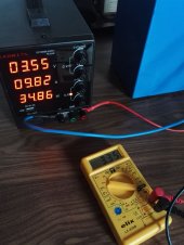
Yes i know that but i was talking about the voltage on the power supply that is also dropping over time. Is this normal ?
Initially, it was set on 3.6v. Now it is 3.55v
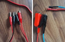
Leave it alone. It knows what the target voltage is, as long as you set it for constant voltage. The leads are to be connected after the settings are in place. Also, the wires that came with the power supply are notoriously wimpy. Creating your own set of larger gauge wires with ring terminals often results in faster charging.
 Totally unbalanced.
