diy solar

diy solar

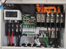
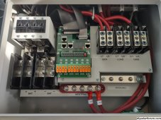
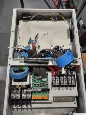
Unboxing of Deye 16K Hybrid Inverter

The documentation from Deye and SunSynk has done a pretty bad job in describing how to perform a Neutral to Earth/Ground bonding when the 16K Hybrid Inverter is operating in "Island Mode" (When GRID is disconnected) and needs N/G bonding.

Keith from SunSyn has posted a YouTube video that describe on how to wire up a N/G bonding, without a schematic and is difficult to implement.

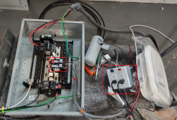
It's said Picture means a thousand words. So here we are, below is a picture of how to wire up a Neutral/Ground bond using a standard "Normally Open" contactor.

1. The example uses a 16 bucks din-rail "Normally Open" type Contactor available on Amazon.
2. Connector 7,8 a dry contact for Generator signal control line, will be used as the control signal for "Island Mode"
3. In the "Advanced Function" menu, CHECK the "Signal Island Mode".
4. When the #3 is enabled, the port 7,8 will be enabled to ON state when the GRID is UP. It will be OFF when GRID is DOWN.
5. You can use a multi-meter set to TONE TEST to confirm a continuality tone when GRID is up. NO tone when GRID is down.
6. In the diagram below, I will be using the EU standard wire color code. L=Brown N=Blue G=Green
7. A "Normally Open" type Contactor is used in this example.
8. Wire 7 to A2 (Neutral return)
9. Wire 8 to Neutral on the LOAD L,N input.
10. Wire N to R2 of the contactor
11. Wire G to R1 of the contactor
12. Wire L to A1 of the contactor.

Here's how this schematic works. When the GRID is connected and the "Signal Island Mode" is enabled in the Advanced Function menu. The port 7,8 signal will power the Contactor via A1 (Live) and A2 (Neutral return), which in turn will keep the R1 and R2 of the contactor "OPEN" and disabled N/G bonding. When GRID power is lost, power to the A1 & A2 will be lost and become "OPEN". The coil of the contactor will be CLOSED and R1 & R2 will be energized and bond the Neutral and Ground wire. When GRID Power is restored, which will take a minute. A1 & A2 will be ON once again and will disable R1 & R2; the N/G bond will be disconnected.

Hopefully, this will help the DIYer in the 230V world. In the US, the Neutral to Ground bonding is always enable by NEC code at the main entrance panel and don't have to worry about this. ?

View attachment 136766
this is exactly how I did it and it is currently working as intended. Nice one for making the diagram that will save a lot of people a lot of time!
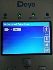
Out of interest does anyone know what the option in advanced settings that is labeled: ATS with a tickbox next to it and on or off in a box next to it does? There is no mention of it in the manual at all? Should it be ticked or not? and what does the option for on/off do?
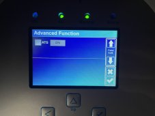
B0FBACB1-8231-4873-8786-6E2A346B745B.jpeg
 
found this in a newer manual for a different model, which is about as clear as mud...

Screenshot 2023-02-25 at 22.10.17.png
 
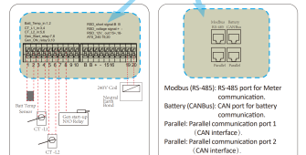
With the latest 16K Firmware, the option is in the last page of the "Advanced Function Menu". This do us no good if you have an "older" version of the IO circuit board. Pilotdrh has posted earlier in the thread, Deye does provide an option of replacing multiple circuit board at your own dime, just to have the newly added ATS port 19,20 that will output a 230V to drive a Standard Reply instead of a Contactor. Remember the new circuit board will have additional wiring to provide the AC 230V output, so is not just merely replace the IO board. Does it worth the time, effort and Money to have this feature or simply wired a contactor using the provided dry contact on port 7,8 that does the same sh*t ?


Latest 16K firmware provides the ATS 230V output on Port 19,20 that DOES NOT EXISIT on my 16K inverter. ?
1677368416558.jpeg

Pilotdrh has posted the question to Deye on the missing ATS port 19,20 and here is their reply.
1677368010579.png

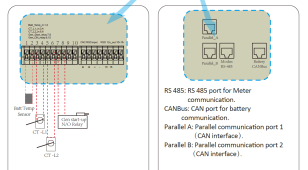
1st generation of the 16K without ATS port 19,20. Tell tail sign is the Battery CAN Bus port is isolated to the right
1677368059548.png

Latest generation of the 16K with the AST Port 19,29 Tail tell sign, the Battery CAN Bus port is now situated at the top right next to the ModBus RS485 port
1677368129822.png

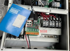
Ed Mek post pics of his 16K, the latest version that contain the ATS port 19,20. He's in the US and probably don't need this N/G bonding thingy as his main breaker panel will have the N/G bond by default per NEC code requirements in the US.
1677368311622.png
 
Last edited:
Greeting All,

Thanks for those that have been following this unboxing and installation of a Deye 16 Hybrid Inverter at 1/3 the price of it's half brother the Sol-Ark 15K with an equally as powerful and reliable hardware/software alternative platform. More bang for the bucks and great for DIYers. The Deye is a more capable build like a tank platform compared with the slightly cheaper and less capable EG4, MPP Solar and Growatt ES500 series inverters. Deye does provide Support Engineer to answer questions via WhatsApp and hardware support with replacement. I've had good experience working with the Deye engineering folks.

The Deye 16K is a single phase 230V/240V platform that can be wired to the US GRID 240V single phase. It does come with a big 300A CT (current transformer) to monitor GRID BUY/SELL. In order to use 120V split phase load, an Autotransformer is required to provide the Neutral wire, a return path for spend/use current from the Hot/Live leg of the circuit and safety to support Arch and Ground fault.

I've setup a Siemens 100A main breaker panel. The 16K LOAD output is wired directly to a modified Growatt 11.4KW Split Phase Auto Transformer 80A input breaker, which I've posted the modification to increase the passthrough to 80A @240v ~ 19.2KW. The modification could be further be enhanced to provide passthrough up to 125A @240v ~ 30KW. For this test, I have used two AFCI/GFCI combo 20A breaker that are wired directly to 2 x 20A receptables wired to L1 and L2 to provide a balanced Split Phase test load. The test platform were installed in the garage and hence limited to just 2 x 120V appliance. In the capacity stress test, a Level 2 48A x 240V EV Charger is used. For the Split phase test, L1 a 20A space heater were used and L2 a Heat gun.

Before the test start, I've wired the Neutral wire from the massive GRID provider transformer mounted on the pole to the Panel's Neutral. I've posted earlier in this tread, prior to the purchase of the Auto Transformer, I could obtain 120V Split Phase output using the GRID Neutral wire and posted pics of this. For this test, I've installed a pair of Siemens 20A AFCI/GFCI combo breaker to verify if using the GRID Neutral will NOT work, which I already know that IT WILL NOT based on the principle of how does a combo breaker electronics detect Ground fault and tripping the circuit to provide safety against Electrocution. The GFCI electronics circuit board on the breaker constantly monitors current flowing through a circuit, from L1/L2 to Neutral. If the current flowing into the circuit differs by a very small amount (as little as 0.006A) from the returning current, it will TRIP the BREAKER. In the 1st test, the L1 & L2 are provided by the locally installed transformer while the Neutral is from the GRID's Neutral, with L1 & L2 wired to a AFCI/GFCI combo breaker, the circuit WILL NOT POWER UP as it is unable to monitor the current flow. The LED will not light up and the breakers WILL NOT TURN ON. If the regular 20A breaker is being used, it will provide 120V split phase, it is certainly NOT ADVISIBLE especially with NEC code, all Living spaces MUST BE installed with AFCI Breaker to prevent ARCH fault that causes 80% of the death in fire. While any area within 6 feet of water/wet area GFCI breaker/outlet MUST BE installed to provide SAFETY AGAINST GROUND FAULT. The GRID provided Neutral was removed and installed with the Neutral from the Auto transformer and both breaker power up right and LED on the breaker light up immediately. I've used a GFCI electronics tester to simulate a ground fault and it TRIP the combo breaker immediately. Works as intended to provide safety and piece of mind.

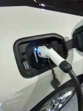
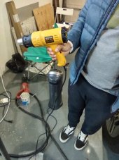
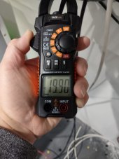
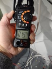
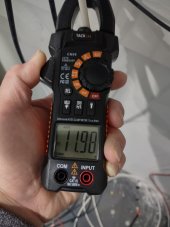
The 16K Stress Test in itself is pretty straight forward. The Level 2 EV charger is wired to a 60A double pole breaker. The Charger was configured to provide max output of 48A * 240V ~ 11.52KW. The space heater were wired to L1 of the 20A AFCI/GFCI combo breaker and the Heat gun is wired to L2 of the 20A AFCI/GFCI combo breaker. I powered up both 120V appliance and took measurement the current draw on L1, L2 and Neutral wire from the transformer. The space heater set set to HIGH and draw a constant 19.9A * 120V ~ 2,388W and the Heat gun is set to high and draw a constant 7.94A * 120V ~ 952.8W. The Neutral from the auto transformer measured 11.98A. Since both test device are wired to L1 & L2 the current returning on the Neutral is this calculated as 19.9A (L1) - 7.94A (L2) ~ 11.96A instead of 27.84A. The transformer specs is rated at L-N 42A@240VAC ~ 5,000VA. When wiring 120V circuit, is highly advisable to balanced the Split Phase load by installed breakers on L1 and L2. On a balanced panel, the 240V from the combine L1 L2 120V will return the current to source during the Alternating phase of the 240V circuit and hence WILL NOT used the Neutral to return the current to source. Hence, a 5,000VA Split phase is sufficient for most household load if the load are balanced on the panel. All 240V load will be just passthrough on the transformer. I then startup the EV charger and the 16K were pull 13.30KW from the LFP battery bank to power the 12.53KW load, everything runs smoothly. The modified Growatt 11.4KW transformer were able to handle the large load as I've calculated 19.2KW flawlessly. This could be modified to support MAX of 125A ~ 30KW ???

***** continuation on the next message as forum limit to just 10 pics ******


Whole House Load Panel are wired to the output of Parallel 2 x Deye 8K with 51.2KW 5 x 200A LFP Battery , the GRID input is provided by
Deye 16K.
1677562210876.png
Deye 16K Load output with 107.52KW 7 x 300A LFP Battery configured as a 24x7 standby Solar Generator and Split-Phase output from a Modified Growatt 80A 19.2KW Autotransformer, simulating as Grid input to the pair of Parallel Deye 8K.

1677562331482.png

Live Capacity test of the Deye 16K off-grid with 1. Level 2 240Vx48A EV Charger 2. 120V Space heater 3. 120V Heat gun.
1677560260235.jpeg

The 100A test panel wired up with two separate 20A AFCI/GFCI combo 120V breaker and two GFCI receptables wired to L1 and L2.
1677560137533.png

Level 2 48Ax240V EV charging at max current

1677561093085.jpeg
120V appliance. Heat Gun and Space Heater on balanced L1 and L2 breaker.
1677559728845-png.137223
1677568677165.jpeg

L1 Load ~ Spacer Heater at Hi full blast consuming 19.9A

1677559777924-jpeg.137224
1677568696074.jpeg

L2 Load ~ Heat Gun consuming 7.94A

1677559796324-jpeg.137225
1677568715391.jpeg1677560137533.png1677560260235.jpeg1677561093085.jpeg1677561522123.jpeg1677561531807.jpeg1677562210876.png1677562331482.png1677568677165.jpeg1677568696074.jpeg1677568715391.jpeg
 
Last edited:
The 16K was purchase with the idea of replacing the pair of Parallel Deye 8K Split phase with 51.2KW of LFP Battery backup. When I initially sized up the LFP battery based on 3 days of backup on the assumption of 3 days of cloudy days. With the 2022 Heat Wave, the battery run out of juice and I've to pull power from the GRID on multiple days. I toy with the idea of building a massive Clean Solar based Backup Generator. I hated those noisy and dirty gas based generator. I start testing by wiring the 16K to the LOAD output of the 2 Parallel Deye 8K and see if it will provide the correct frequency to the GRID input of the 16K. And sure enough it runs flawlessly since early on when I started posting on this forum. Now that I have completed the LOAD stress test on the 16K and again it perform flawlessly working under heavy load. I finally have help to mount the super heavy 16K onto the wall and complete the final wiring. Just in time for a week of continuous rain in the normally Sunny Southern California. This past Monday, the 51.2KW battery bank will drawn down to 25% SOC and stop discharging and instead start pulling power from the "GRID INPUT" provided by the 16K with 107.52KW LFP Battery bank. It works flawlessly and I don't have to flip the 200A breaker on the main panel. With the 107.52KW LFP battery, I'll be able to charge the EV at full 48A in about 5 hours from 35% to 85% whenever I need instead of breaking the charge over a couple of days using Solar.

Overall, this project has met all my expectation and works flawlessly as designed. From the get go when I first installed solar, I have decided NOT to have it Grid-Tie as I've plan to used LFP battery to store the excess energy produced from the PV system instead of Net-Meter with the GRID. The California CPUC were in the process of updating the current NEM 2.0 to 3.0 extreme changes to the GRID provider credit for excess energy feedback. Besides, the plan will be changed to TOU (Time-Of-Use) rate where it will double the rate from $0.26KW to $0.56KW between 4-9PM and a higher NON-USAGE rate. I'm glad on my decision to be Energy independent, just this week, more than Eighty Thousands families lost power during this extreme "Atmospheric River" phenomenal that hit California a second time.

On closing of this thread, will this works for you ? It really depends on, how comfortable are you at working with electrical system without much hand holding. If you're not comfortable, your best bet is to have a licensed electrician and spend some bucks with the folks in Plano, TX. Since my initial system were permitted, I've not concerned adding the 16K to the mix. Most of the folks that critique the Deye 16K being not UL listed and hence "dangerous" to be installed. Yet some have posted pics of cheap Chinese Battery that are not UL listed or DIY battery with cheap BMS. Though the 16K is not UL listed, it was certified by CE and TUV world wide standard world similar to UL 1741 specification. Most of the components used in the 16K are UL certified and you'll see UL logo on those component. Besides, it will pass UL 1741 test if one is willing to fork 40K for the compliance test with UL Lab as it's half brother the 15K did. The 15K is the same sh*t in a different cloth and some hand holding. Unlike like before where calls will be answered by a support dude in Plano, TX, it goes to voice mail and you'll have to wait for a call back. The Growatt transformer is UL 1741 listed. Besides, I have followed NEC code and apply best practice relating to safety.

Good luck and be safe ?


Neutral from Autotransformer Balanced Load 11.98A ~ L1-19.9A - L2-7.94A

1677570836136.jpeg

I'm totally Net-Zero and Carbon Neutral on my Energy consumption. ?

1677561522123-jpeg.137232


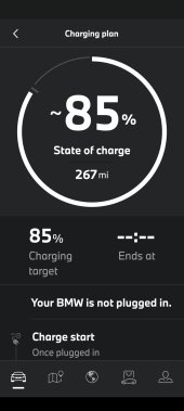
Fully charge to preset 85% SOC by the Deye 16K in about 5 hours. ?
1677572897038.jpeg

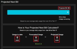
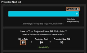
Oh well, I have to pay $5 bucks for less than min. usage. Duh ?

1677561531807-jpeg.137233
 
Last edited:
But when you get a chance: a detailed diagram on your modification/wiring of the Growatt transformer, Please.
 
The 16K was purchase with the idea of replacing the pair of Parallel Deye 8K Split phase with 51.2KW of LFP Battery backup. When I initially sized up the LFP battery based on 3 days of backup on the assumption of 3 days of cloudy days. With the 2022 Heat Wave, the battery run out of juice and I've to pull power from the GRID on multiple days. I toy with the idea of building a massive Clean Solar based Backup Generator. I hated those noisy and dirty gas based generator. I start testing by wiring the 16K to the LOAD output of the 2 Parallel Deye 8K and see if it will provide the correct frequency to the GRID input of the 16K. And sure enough it runs flawlessly since early on when I started posting on this forum. Now that I have completed the LOAD stress test on the 16K and again it perform flawlessly working under heavy load. I finally have help to mount the super heavy 16K onto the wall and complete the final wiring. Just in time for a week of continuous rain in the normally Sunny Southern California. This past Monday, the 51.2KW battery bank will drawn down to 25% SOC and stop discharging and instead start pulling power from the "GRID INPUT" provided by the 16K with 107.52KW LFP Battery bank. It works flawlessly and I don't have to flip the 200A breaker on the main panel. With the 107.52KW LFP battery, I'll be able to charge the EV at full 48A in about 5 hours from 35% to 85% whenever I need instead of breaking the charge over a couple of days using Solar.

Overall, this project has met all my expectation and works flawlessly as designed. From the get go when I first installed solar, I have decided NOT to have it Grid-Tie as I've plan to used LFP battery to store the excess energy produced from the PV system instead of Net-Meter with the GRID. The California CPUC were in the process of updating the current NEM 2.0 to 3.0 extreme changes to the GRID provider credit for excess energy feedback. Besides, the plan will be changed to TOU (Time-Of-Use) rate where it will double the rate from $0.26KW to $0.56KW between 4-9PM and a higher NON-USAGE rate. I'm glad on my decision to be Energy independent, just this week, more than Eighty Thousands families lost power during this extreme "Atmospheric River" phenomenal that hit California a second time.

On closing of this thread, will this works for you ? It really depends on, how comfortable are you at working with electrical system without much hand holding. If you're not comfortable, your best bet is to have a licensed electrician and spend some bucks with the folks in Plano, TX. Since my initial system were permitted, I've not concerned adding the 16K to the mix. Most of the folks that critique the Deye 16K being not UL listed and hence "dangerous" to be installed. Yet some have posted pics of cheap Chinese Battery that are not UL listed or DIY battery with cheap BMS. Though the 16K is not UL listed, it was certified by CE and TUV world wide standard world similar to UL 1741 specification. Most of the components used in the 16K are UL certified and you'll see UL logo on those component. Besides, it will pass UL 1741 test if one is willing to fork 40K for the compliance test with UL Lab as it's half brother the 15K did. The 15K is the same sh*t in a different cloth and some hand holding. Unlike like before where calls will be answered by a support dude in Plano, TX, it goes to voice mail and you'll have to wait for a call back. The Growatt transformer is UL 1741 listed. Besides, I have followed NEC code and apply best practice relating to safety.

Good luck and be safe ?


Neutral from Autotransformer Balanced Load 11.98A ~ L1-19.9A - L2-7.94A

View attachment 137239

I'm totally Net-Zero and Carbon Neutral on my Energy consumption. ?

1677561522123-jpeg.137232


Fully charge to preset 85% SOC by the Deye 16K in about 5 hours. ?
View attachment 137240

Oh well, I have to pay $5 bucks for less than min. usage. Duh ?

1677561531807-jpeg.137233
Posted my setup, If you have a spare few mins I'd appreciate if you could cast your eye over it, if you see anything stand out as incorrect please don't hold back.

 
All, those who have ordered from alibaba, could you please share DM the vendor/URL for both the 16KW inverter and the transformer? Appreciate your help..
 
All, those who have ordered from alibaba, could you please share DM the vendor/URL for both the 16KW inverter and the transformer? Appreciate your help..
Maybe contact the Idiot:

 
Gla
Here's how I intend to wire up for Split-Phase 120V~240V 60 HZ application.

View attachment 121002
16K LOAD output L N wired to the Victron 100A Autotransformer L N 100A double pole circuit breaker
View attachment 120996
Victron 100A Autotransformer ?


Earlier this year, there's a big discussion about installing of the Growatt ES500 with SolarEdge 5KW Autotransformer and the issues of Ground Bonding issues. Questions of Losing the Neutral when the Autotransformer is down and damages that will be cause to all 120Vs circuit breaker on the LOAD panel, suddenly becoming 240V and damage/frying to all 120V connected appliance. There were suggestions of using 2 Autotransformer and using relays to monitor the Neutral line and so on. Just a complex mess and no real solution to the problem when loosing the Neutral wire.

Well, in my application, with a larger 24K Autotransformer load balancing the LOAD output of the Deye 16K's 16KW, The LOAD panel will be wired directly from the Victron's output L1, L2 and N terminals. As such if the Victron or the Deye 16K is down, all circuits on the LOAD panel will be down automatically, period. No damage will be caused to both the 240V and 120V circuits. The Victron has a built in Earth/Ground relay, allowing for Neutral to Ground bonding. Simple and Elegant solution to a Chicken or an Egg problem ???
 
Great thread...

Reading some suggestions by Timselectric, was my original plan before the SRNE...

Single phase + Isolation transformer.
Misterbubbacat seems to got it working...the loads balancing looks excelent and the amps, its future proof...thats a hurdle on some of the split designs...

Great thread to learn a few little things and advices ?
 
Greeting All,

Everything is humming along. I've ditched the somewhat limited 5KW 120VAC only Growatt Autotransformer and have successfully Reversed Engineered the 16K, this early spring. I just hated the low humming buzzing noise of a traditional transformer. The 16K is operating in UL1741 US Split-phase 120V/240V 60HZ natively, while retaining EU 230V GRID function with User selectable GRID type via built in Firmware. It is a truly International Hybrid Inverter.

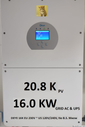
The 16K is the ONLY highest 16KW AC/DC output for a Low Voltage 48VDC Hybrid Inverter on the market with a 200A Pass-through, GRID AC 16KW and OFF-GRID Backup LOAD (UPS Mode) 16KW and PV 20.8KW.

Maybe I should names is as a 20.8K PV, borrowing a market naming BS from SS James's LuxPower rebranded 18k PV with only 12KW GRID AC and BACKUP LOAD and Tom's Deye rebranded SA 15K with only GRID AC 15KW and BACKUP LOAD 12KW ???


1699933622294.png

Before, 16K with limited 5KW 120V via the Growatt 11.4K Split Phase Transformer ATS 11400T-US that I've modified the 240VAC pass-through to 19.2KW. If anyone needs an Autotransformer, is available for sale in like new condition. PM me.

1699934207541.png

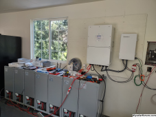
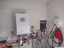
After, 16K running my whole house Totally OFF-GRID in UL1741 120/240VAC 60HZ, Reversed Engineered in California by yours truly. Pardon the mess, it's always work in progress in the Lab. ??
1699934419158.jpeg
 
Last edited:
Original 16K Single-phase EU 230V from the factory
1699946295917.png

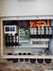
Reversed Engineered 16K version 1, implemented native US Split-phase 120V/240V 60HZ with hardware modification with OEM UL certified components to provide system Neutral, while maintaining factory Single-phase EU 230V. User configurable Firmware to support All Worldwide GRID standards.
1699946339699.jpeg

Reversed Engineered 16K version 2 with US Split-phase support for the latest version of the Deye 16K. Support both Single-phase & Split-phase via Firmware. Professional Factory OEM look and labeled properly.
1699946647598.jpeg

Scary, where's the Circuit board ???
1699948112065.jpeg
 
Last edited:
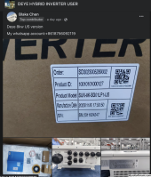
Nice work :) How did you do it? Also I have seen some chinese sellers advertising US versions of Deye on Facebook. Sol-Ark exclusivity might be gone now judging by the production date

1699948643597.png
 
Nice work :) How did you do it? Also I have seen some chinese sellers advertising US versions of Deye on Facebook. Sol-Ark exclusivity might be gone now judging by the production date

View attachment 177654

That's just the 5K & 8K only. There's no US version of 16K available anywhere in the world period. BTW, authorized Deye distributor is not allowed to ship US Split-phase products to the USA. Deye tracked the Serial Numbers of the units and know where the units come from, they have a kill switch in the Firmware to shut the Inverter down, if our friend in Plano TX complaint to the mothership. SA is still the only Exclusive OEM distributor for the US market. As part of the new Deye, SA exclusive agreement executed on 07/01/2023, Deye will manufacture and distribute the US Split-phase products only to the South America. Tommy lost the Exclusive in South American market but gain access to the latest & greatest monster inverters from Ningbo and MW Battery Storage system. He got plenty of fish to fry.

Buyer beware.
 
Last edited:
Back
Top