diy solar

diy solar

Using DC to DC charger to precharge inverters?

Turning OFF the inverter and disconnecting the inverter are two different things. Turning the inverter off still has it connected to the DC side, so the capacitors are and remain fully charged.
Yupp but I'm assuming when people are turning off their inverters they're turning off their DC system as well. whenever they're not using it.
 
But its very very rare I need close to 200A of 48V (10kw) power in an RV.
At 10kW output inverter will pull close to 250A on DC side due to conversion loss. If you have air conditioners in your RV without soft starters you may have enough surge current to go past 400A momentary load on DC side.
 
I had an issue over the weekend where my batteries BMS's were tripping and needed to precharge the 2x5000w Quattro inverters which have massive capacitators. I know the SOK batteries have a precharge setting but it a bit complicated and I need to google it everytime.... I really need to print a label with any instructions and just stick to the batteries. I messed with the batteries but was having an issue keeping them out of SCP even with breaker off and when they did I messed up turning on the precharge option.

So I turned the key on my RV to on and used my 4x400w 24/48 DC to DC chargers and the inverters powered up instantly with no issues. This happened a few times yesterday and each time it worked perfectly.

I know the capacitators use a ton of power for milliseconds to charge which cause the issues with the BMS thinking they're short circuiting. But is it safe to use a DC to DC charger? Should the battery breaker be off or on or does it not matter? The chassis batteries are 4 huge lead acid starter so inrush shouldn't be an issue with those, just unsure how it affects the DC to DC converters. Also Victron only makes max 400w for the 24/48 so even though I have 4 I worry it could be using 1 for that split rush and unsure how much power the capacitators actually pull, or if the DC to DC converters safely limit the power so it doesn't matter.
Another thing is if you have PV connected and it’s sunny out just turn on your PV and it should charge the capacitors or you can use Grid also.
 
At 10kW output inverter will pull close to 250A on DC side due to conversion loss. If you have air conditioners in your RV without soft starters you may have enough surge current to go past 400A momentary load on DC side.
It should be close to 220A as even at max load it should be around 90% (max is 94% for my 5kw's). below is a datasheet for the 3kw models so the 5kw is overrated thus low efficiency

LRA on my largest AC is 57amps and although I have 6 AC's (2 are on my 3rd quattro on a backup system) I think the microair thermostat stagger starts them. 57amp at 120v is 137amp at 50v. At 12V its 526A though so you're spot on.
 
Another thing is if you have PV connected and it’s sunny out just turn on your PV and it should charge the capacitors or you can use Grid also.
yupp but I'm assuming the same concern applies since its also a DC-DC converter. Although the MPPT might need DC power to turn on, I can't remember.
 
It should be close to 220A as even at max load it should be around 90% (max is 94% for my 5kw's). below is a datasheet for the 3kw models so the 5kw is overrated thus low efficiency
https://www.victronenergy.com/uploa...ting-operating-temperature-and-efficiency.pdf
On page 4 in that document it shows 80% efficiency of 3kVA inverter at 5kVA. It appears that efficiency degrades linearly at 3% per 1kVA so at 2x rated load it should be 77%. We can extrapolate it to 5kVA rated inverter being 77% efficient at 10kVA which would require 260A at 50V.
 
On page 4 in that document it shows 80% efficiency of 3kVA inverter at 5kVA. It appears that efficiency degrades linearly at 3% per 1kVA so at 2x rated load it should be 77%. We can extrapolate it to 5kVA rated inverter being 77% efficient at 10kVA which would require 260A at 50V.

Ahhhh I have dual 5kw inverters in split phase so 10kw would be at the 86.7% efficiency if not more as higher inverters should be more efficient. I just tried it as I have my Tesla connected to my RV so switched off shore and turned on the charger. This was over about 2 minutes and the battery number is from the batteries BMS so is actual but could be off a few seconds. the log file should be a lot more accurate than the images. I'm not home so worried about turning it up too high and losing remote access to it as I don't pull nearly this much power so haven't fully tested it.

5845.348​
5373​
0.919192493​
8195.904​
7222​
0.881171863​
8223.6​
7260​
0.88282504​
8299.692​
7280​
0.877140983​
5386.992​
4979​
0.924263485​
5353​
4932​
0.921352513​
7152.138​
6331​
0.885189855​


1701889511548.png1701889548388.png
 
On page 4 in that document it shows 80% efficiency of 3kVA inverter at 5kVA. It appears that efficiency degrades linearly at 3% per 1kVA so at 2x rated load it should be 77%. We can extrapolate it to 5kVA rated inverter being 77% efficient at 10kVA which would require 260A at 50V.


Forgot the 150-200w solar I was making. Numbers all above 90% Average 92.635121 efficiency.
5845.348​
5373​
0.951420029​
8195.904​
7222​
0.902648001​
8223.6​
7260​
0.904605263​
8299.692​
7280​
0.899354787​
5386.992​
4979​
0.962313046​
5353​
4932​
0.955813953​
7152.138​
6331​
0.908303394​
 
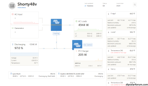
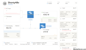
Looking at the pictures you provided it shows efficiency of 89% at 4944W and 86.3% at 6562W.
 
Looking at the pictures you provided it shows efficiency of 89% at 4944W and 86.3% at 6562W.
The VRM website doesn't update everything at the same time so when the numbers are changing like crazy they can be wrong. I turned off the tesla charger but kept it on invert only mode so has lower numbers. There was an issue at 14:06 when I was pulling over 8kw from the inverter which it reset the AC. I got a low DC voltage issue so maybe the wiring or something.

There's about a 70w idle consumption so efficiency at low wattage sucks. This is with the solar added. I believe there's a delay in the BMS reporting or something so you kinda need to take an average of a few results combined.

2023-12-06 14:02:38
1776.975​
1715​
0.965123​
2023-12-06 14:02:53
5085.376​
5373​
1.056559​
2023-12-06 14:02:54
6039.348​
5373​
0.889666​
2023-12-06 14:03:05
8383.904​
7222​
0.861413​
2023-12-06 14:03:28
8414.6​
7260​
0.862786​
2023-12-06 14:04:04
8500.692​
7280​
0.856401​
2023-12-06 14:04:34
5591.992​
4979​
0.89038​
2023-12-06 14:05:04
5539​
4932​
0.890413​
2023-12-06 14:05:29
7330.138​
6331​
0.863695​
2023-12-06 14:06:04
7646.458​
6600​
0.863145​
2023-12-06 14:06:29
8568.704​
7405​
0.864191​
2023-12-06 14:06:30
8568.704​
7405​
0.864191​
2023-12-06 14:06:31
8572.704​
1172​
0.136713​
2023-12-06 14:06:35
-51.694​
0​
0​
2023-12-06 14:06:38
31.41​
0​
0​
2023-12-06 14:07:01
10.779​
0​
0​
2023-12-06 14:07:05
2111.64​
3616​
1.712413​
2023-12-06 14:07:21
3780.486​
3414​
0.903058​
2023-12-06 14:08:04
1831.115​
1675​
0.914743​
2023-12-06 14:08:30
1796.999​
1645​
0.915415​
2023-12-06 14:09:04
305.544​
232​
0.759301​
2023-12-06 14:09:32
306.316​
240​
0.783505​
2023-12-06 14:10:04
1912.485​
1857​
0.970988​
2023-12-06 14:11:04
2116.749​
1918​
0.906106​
2023-12-06 14:12:04
610.344​
480​
0.786442​
2023-12-06 14:13:04
3637.499​
3328​
0.914914​
2023-12-06 14:14:04
3642.668​
3315​
0.910047​
2023-12-06 14:15:04
2143.108​
1894​
0.883763​
2023-12-06 14:16:04
2117.875​
1915​
0.904208​
2023-12-06 14:16:48
2102.44​
1900​
0.903712​
2023-12-06 14:17:05
2111.154​
1906​
0.902824​
2023-12-06 14:18:04
2127.52​
1912​
0.898699​
2023-12-06 14:19:04
620.89​
475​
0.765031​
2023-12-06 14:19:37
1466.288​
1520​
1.036631​
2023-12-06 14:20:04
2102.722​
1911​
0.908822​
2023-12-06 14:21:05
2116.992​
1902​
0.898445​
2023-12-06 14:22:04
2100.23​
1901​
0.905139​
2023-12-06 14:23:04
616.52​
478​
0.77532​
2023-12-06 14:24:04
2108.504​
1915​
0.908227​
2023-12-06 14:25:04
2107.984​
1904​
0.903233​
2023-12-06 14:26:05
609.497​
470​
0.771128​
2023-12-06 14:27:04
2147.496​
1919​
0.893599​
2023-12-06 14:28:04
2106.952​
1907​
0.905099​
2023-12-06 14:29:04
608.275​
474​
0.779253​
2023-12-06 14:30:04
1573.724​
2179​
1.384614​
2023-12-06 14:31:04
2101.952​
1903​
0.905349​

 
Looking at the pictures you provided it shows efficiency of 89% at 4944W and 86.3% at 6562W.

Here's the voltage and amperage reported on each. The numbers never add up, not sure if its losses in wiring (few feet max) or just reporting differences. Shunt and BMS should be identical


TimeV at inverterA at inverterV at shuntA at shuntV at BMSA at BMSV at solarA at solar
2023-12-06 14:02:38
52.8​
-34.9​
52.7​
-32.1​
53.05​
-29.5​
53.02​
4​
2023-12-06 14:02:53
50.68​
-116.4​
50.8​
-115​
51.38​
-95.2​
51.1​
3.8​
2023-12-06 14:02:54
50.68​
-116.4​
50.68​
-115.6​
51.32​
-113.9​
51.1​
3.8​
2023-12-06 14:03:05
49.44​
-164​
49.54​
-165.1​
50.22​
-163.2​
49.59​
3.8​
2023-12-06 14:03:28
48.96​
-166.3​
49.06​
-167.1​
49.84​
-165​
49.1​
3.9​
2023-12-06 14:04:04
48.76​
-167.9​
48.88​
-168.9​
49.58​
-167.4​
48.94​
4.1​
2023-12-06 14:04:34
49.92​
-108.6​
49.91​
-108​
50.44​
-106.8​
50.06​
4.1​
2023-12-06 14:05:04
49.98​
-107.2​
49.97​
-107.5​
50.5​
-106​
50.15​
3.7​
2023-12-06 14:05:29
49.26​
-143.3​
49.32​
-144.4​
49.98​
-143.1​
49.41​
3.6​
2023-12-06 14:06:04
49.06​
-150.5​
49.16​
-152​
49.79​
-150.2​
49.39​
3.4​
2023-12-06 14:06:29
48.72​
-170.6​
48.84​
-172.6​
49.48​
-169.8​
49.08​
3.4​
2023-12-06 14:06:30
48.72​
-170.6​
48.84​
-172.6​
49.48​
-169.8​
49.08​
3.4​
2023-12-06 14:06:31
45.48​
-21.1​
36.1​
-99.1​
49.48​
-169.8​
45.03​
3.8​
2023-12-06 14:06:35
52.04​
0​
52.4​
2.3​
52.07​
4.2​
52.1​
3.2​
2023-12-06 14:06:38
52.1​
0​
51.91​
2.5​
52.15​
2.6​
52.17​
3.2​
2023-12-06 14:07:01
52.44​
0​
52.26​
2.8​
52.49​
2.9​
52.5​
3.1​
2023-12-06 14:07:05
50.9​
-76.6​
50.82​
-78.6​
51.28​
-38​
51.09​
3.2​
2023-12-06 14:07:21
50.92​
-72​
50.84​
-72.4​
51.31​
-70.6​
50.98​
3.1​
2023-12-06 14:08:04
51.8​
-34.8​
51.71​
-30.8​
52.05​
-30.3​
51.9​
4.9​
2023-12-06 14:08:30
51.84​
-35.4​
51.75​
-31.5​
52.09​
-31.1​
51.98​
3.4​
2023-12-06 14:09:04
52.6​
-5.6​
52.42​
-3.4​
52.67​
-3.2​
52.65​
2.6​
2023-12-06 14:09:32
52.66​
-5.8​
52.48​
-3.7​
52.74​
-3.4​
52.72​
2.4​
2023-12-06 14:10:04
51.84​
-38.8​
51.77​
-37.3​
52.13​
-34.5​
52.01​
2.2​
2023-12-06 14:11:04
51.74​
-40.2​
51.67​
-39​
52.03​
-38.3​
51.85​
2.4​
2023-12-06 14:12:04
52.52​
-10.1​
52.38​
-9.9​
52.64​
-9.6​
52.59​
2​
2023-12-06 14:13:04
51.16​
-69.4​
51.1​
-69.3​
51.53​
-68.3​
51.27​
2.3​
2023-12-06 14:14:04
51​
-69.8​
50.94​
-69.4​
51.38​
-68.6​
51.11​
2.3​
2023-12-06 14:15:04
51.68​
-39.2​
51.55​
-39.4​
51.91​
-38.8​
51.73​
2.5​
2023-12-06 14:16:04
51.78​
-40.4​
51.69​
-38.1​
52.05​
-37.5​
51.89​
3.2​
2023-12-06 14:16:48
51.76​
-40.1​
51.69​
-37.6​
52.05​
-36.8​
51.9​
3.6​
2023-12-06 14:17:05
51.74​
-39.9​
51.67​
-38.3​
52.02​
-37.7​
51.86​
2.9​
2023-12-06 14:18:04
51.74​
-40​
51.65​
-38.5​
52.04​
-38​
51.89​
2.9​
2023-12-06 14:19:04
52.5​
-10.3​
52.34​
-9.6​
52.62​
-9.5​
52.57​
2.3​
2023-12-06 14:19:37
51.96​
-10.2​
52.4​
-9.9​
52.17​
-26.4​
52.22​
1.7​
 
Probably readings are not time synchronized. Calibration could be off as well.
I believe Victron auto time syncs everything, it should. Calibration shouldn't matter either because it should be shunt types and recording the electrons passing through at a point of time, even CT type would be the same. Calibration just fixes the 0 and 100 as it needs a start or end point to calculate SoC.

I think its just a reporting delay of milliseconds which affects instant logging. I'm assuming others have the same issue
 
Calibration shouldn't matter either because it should be shunt types and recording the electrons passing through at a point of time
Current shunt is a resistor of very low value. For example 500A 50mV shunt = 0.0001 ohm. Making such resistor without error is difficult. That's why shunt error needs to be calibrated inside measuring device.
 
Current shunt is a resistor of very low value. For example 500A 50mV shunt = 0.0001 ohm. Making such resistor without error is difficult. That's why shunt error needs to be calibrated inside measuring device.
Smart Shunt resolution and accuracy 0.01A +- 0.4 % I have a lynx1000 shunt and couldn't find its accuracy. In cases I'm multiple amps off.

I posted the question in victron support so guess ill see if there's anything I'm missing.

 
Another option for you is to use a small solar panel with a Voc that is ~ close to your bus bar voltage. It does not even need to be at full voltage - just hitting 75% is usually enough.

No need to even have a charge controller - just direct attach through a breaker. Flip it on and it will self limit the charge current and voltage intrinsically.

In a 12 or 24 volt system, you can also use a solar charger that will turn on with zero battery voltage, such as a bogart PWM unit.
Same original question still applies, is it safe for the panel or MPPT/PWM to handle that inrush current?
 
Same original question still applies, is it safe for the panel or MPPT/PWM to handle that inrush current?

There simply will not be an inrush current at all.

Suppose that you use a nominal 24 volt, 300 watt solar panel, which is fairly healthy size.

The Vmp will be ~ 36 volts and Voc close to 40 volts. Ioc (short circuit current ) will be at most 10 amps from the panels into the inverter caps. These numbers are on the data sheet and on the panel's label on the back of it.

So if you just hook it up directly to the bus bar (via a fuse or breaker ) then the absolute most it can push in the circuit is 10 amps no matter how large the inverter capacitors are since a panel like that simply cannot generate more current than the Ioc (short circuit current ).

The voltage will self limit to the Voc, so roughly 40 volts after a few minutes because this is also an intrinsic self limiting capability of all solar panels. In a 24 volt system, just use a nominal "12 volt style" panel, which will self limit to ~ 22 volts. (the built in Voc of the panel )

Once the inverter caps are pre-charged to the bulk of the Vbat, then the battery BMS is much less likely to trip when you turn on the main breakers. (Turn off the solar panel connection first ) If it does, then turning the breaker off for 5 seconds and back on will usually fix the issue.

Not all solar controllers can start up with zero battery voltage but I know that the bogart can because I use them on some things. The presence or absence of a solar controller will not increase what the solar panel can deliver amps wise. The bogart self limits to 30 amps no matter the conditions if that is helpful.

You can use a much smaller panel to do this as well, it will just take a few minutes longer. All that matters is the Voc being roughly correct. For instance a 30 watt panel might self limit to an Ioc of 1 amp, so it is just a matter of patience.

In a pinch, you can even use this trick to jump start your vehicle starter battery with a solar panel as long as you use a volt meter to keep the starter battery voltage under ~14 - 15 volts.
 
Last edited:
I made a little test fixture from left over parts to more clearly explain what I mean by using the solar panel to pre-charge the inverter caps.

I had a few challenges with the images but hopefully the concept makes sense.

 
Back
Top