OK, so just to be clear you shorted Positive Microinverter input cable (MC4) to negative Microinverter cable (MC4) and read 0.1 Ohms for the farxsides of the cable that would connect to the battery, correct?I measured three MicroInverters the best I could get was 0.1 ohms so I reckon 0.05 ohms on them all.
Did this no problem
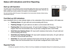
This is the new circuit:
.
View attachment 147295
Do we can call it 0.05 - 0.149 ohms.
Just the amount of inline resistance agt is proving is needed to get the Enphase Microinverters to boot and lock-on correctly.
So you are using the Microinverters to power lightbulbs to calibrate / set the DCDC converters when powering the Microinverter???I am using old style globes (mix 25W to 100W) to get the draw through a 24V inverter pretty close to what I want.
You need to configure the DCDC booster when it is not powering a Microinverter, then check the power you are getting from a microinverter in a second step. No touching the pots whole connected to a Microinverter.
If you do, please don’t touch the one you have working.Using an old party light(s) cord.
The draw is constant but the Boost Converter won't play ball.
I am probably barking up the wrong tree.
.
View attachment 147296 View attachment 147297
Definitely - I just will not touch it for fear of never getting it back.
I used 30VDC.
I might have one more go at it.
You mean you are powering the DCDC booster off of a DC power supply rather than a battery when you are adjusting the pots?I used my bench-top power supply - that is possibly an issue.
That should be OK as long as of the DC power supply is set to match battery voltage, current limit of the DC supply is well over fuse rating of the DCDC booster, and you are not powering a Microinverter when you are adjusting the posts.
Set the pots powering DC loads only and then check the power you are getting with a Microinverter (but no adjustments while connected to the Microinverter).
If you want 150W out of the Microinverter, you will need 150W / 95% = 158W out of the DCDC booster.OK I will try this out.
I was aiming for 150W @ 240VAC to try to assist others.
158W = 30V x 5.27A.
If we assume there is 0.05 Ohms of resistance between DCDC booster and Microinverter, 5.27A will consume 5.27 x 5.27 x 0.05 = 1.4W in I^2R losses in the wires.
So aim for 159.4W = 5.3A @ 30 VDC.
Setting the pot for maximum output voltage of the DCDC booster to 30VDC while powered by your benchtop DC supply and not connected to a Microinverter should be easy using a multimeter.OK I will need to read this a few times & try.
OK Thank you very much. - I will get better at this.
You turn either need to put your multimeter in DC current mode and adjust the current-controlling pot for 5.3A or connect positive and negative leads to a 1 ohm 100W power resistor and monitor voltage across the resistor using your multimeter while you trim the pot.
Voltage across a 1 ohm power resistor > 5.3V means current needs to be reduced.
Volrage across a - ohm power resistor < 5.3V means current needs to be increased.
When you’ve adjusted the current-controlling pot so your multimeter reads 5.3V across a 1 ohm power resistor, y I’ve got the correct trimmer for a maximum of 5.3A.
You can Joe connect the booster to a Microinverter (either power by battery or by your bench-top DC supply and use an AC current clamp to measure AC power output from the Microinverter (of your lightbulbs if you prefer
") ).
).The key thing is yo make adjustments only with DC loads, not a Microinverter. The Microinverter is just a final check that your DC voltsge setting and DC current setting are delivering the power needed to get Microinverter output where you wanted it.
I realize this is a more painful trimming process than what you were using but I’m hoping you find it to be more successful and repeatable…