diy solar

diy solar

Using solar micro inverters with batteries instead of panels

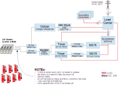
Updated the drawing based on your posts and some logic (very possibly wrong; -) trying to fully comprehend your system:
  1. Moved the CTs (there shouldn't be two circuits exiting the IQ Combiner. Also, the CT positions are odd... usually it's PV, grid, load/home, not as displayed above, so took a stab at what I thought might be likely. You have a 2x in front of them and that's a bit confusing too, so possibly I just don't understand something.
  2. Relabeled Envoy to IQCombiner w/Envoy to make it clearer.
  3. Put the shunt back in as I suspect you haven't had time yet to actually remove it. I know the intent is to remove it, but it adds to the total resistance so important to consider for the sake of the discussion.
  4. Changed out the IQ7A as you mentioned it was a future test.
  5. Indicated the BMS was inside a battery system.
  6. In your drawing above you showed line-side taps, but as that's uncommon here I terminated the IQ Combiner at the load center, if you really have line-side taps should be changed
You mentioned you buy top-shelf batteries. I had assumed you were talking about cells, but now that I know the BMS is in there it make me curious about the system. Does the battery system have it's own on/off switch or breakers? Does it have a precharge system?

1683026344562.png
 
Sorry, I wasn't clear. My intention is to have this functioning when the grid is available. This is an on grid scenario. So the microinverter will function. I just want it to function in the evening by switching the panel out and a 36V battery in.

Why? because the wholesale nature of the electricity plan I'm no means I'm not paid much for solar export during the day (6 cents/KwHr). So I'm better of pushing that energy into batteries or hot water. However what I've seen lately is that, come early evening the price spikes for an hour or so before settling down. Last night it was $2.46 KW/hr for about 1/2 an hour. It's a good time to be either on batteries, or exporting the energy stored earlier.

The microinverters I already have will do that. They just need to be powered.

The Enphase system does this get the IQ8's and the 10T batteries... They also give you Savings Mode, Self-Consumption Mode and Full Backup Mode.

I use the Self Consumption Mode and really don't use grid power anymore but still connected.

I think this is what you are wanting to do???


:)
 
Updated the drawing based on your posts and some logic (very possibly wrong; -) trying to fully comprehend your system:
  1. Moved the CTs (there shouldn't be two circuits exiting the IQ Combiner. Also, the CT positions are odd... usually it's PV, grid, load/home, not as displayed above, so took a stab at what I thought might be likely. You have a 2x in front of them and that's a bit confusing too, so possibly I just don't understand something.
  2. Relabeled Envoy to IQCombiner w/Envoy to make it clearer.
  3. Put the shunt back in as I suspect you haven't had time yet to actually remove it. I know the intent is to remove it, but it adds to the total resistance so important to consider for the sake of the discussion.
  4. Changed out the IQ7A as you mentioned it was a future test.
  5. Indicated the BMS was inside a battery system.
  6. In your drawing above you showed line-side taps, but as that's uncommon here I terminated the IQ Combiner at the load center, if you really have line-side taps should be changed
You mentioned you buy top-shelf batteries. I had assumed you were talking about cells, but now that I know the BMS is in there it make me curious about the system. Does the battery system have it's own on/off switch or breakers? Does it have a precharge system?

@svetz
What program did you use to make this one line drawing? Thanks
 
Three phases? 3 wires going to the grid looks like three-phase, but sourced from devices as shown would be odd.
Sorry. My drawing is not that good.
Three-phase power is rarely used in residences so suspect this might be something lost in translation. I've heard Australia is mostly single phase 230V @ 50 Hz. Possibly phase means "hot" wire or "circuit"?
Definitely - we have three phase.
New houses are single phase.
A 240v microinverter here would have 3 wires, L1, L2, and ground. A three-phase microinverter here would have 4 wires: line 1, line 2, line 3, and ground, and I believe an Austrailian version would have to be the same.
All the Enphase microinverter plugs I have can utilize any one 3 phase.
If you're truly 3-phase power, please confirm.
Definitely
Thanks for confirming the IQ Combiner box, seeing power flow through an Envoy as per the diagram definitely made me believe there was a missing component.
OK.
Will look at this more tomorrow.k
 
Sorry. My drawing is not that good.

Definitely - we have three phase.
New houses are single phase.

All the Enphase microinverter plugs I have can utilize any one 3 phase.

Definitely

OK.
Will look at this more tomorrow.k
You and svetz are doing a good job getting your direct-powered circuit nailed down and documented, but could I ask you to also provide the same level of detail on the one DCDC converter-powered Microinverter you have?

I assume the battery protector switch is at the input of the DCDC converter so what I’m specifically interested to understand is where the timer switch is also on the DC input side of the DCDC converter or whether the timer switch is in between the output of the DCDC converter and the Microinverter.

It would also be helpful on the circuit diagram you are refining with svetz if you could indicate where you placed your multimeter probes to measure 0.1 ohm resistance to the disconnected MC4 connectors and back. I assume you made the measurement from behind the shunt out to the M215 MC4 wire connector and back to the negative connection of the battery (meaning the round-trip measurement did not include the BMS) but a confirmation would be appreciated.

And lastly, it’s pretty clear you have 0.05 - 0.149 Ohms or more of resistance in the path between your battery cells and your direct-powered microinverters, but it would be great to know the equivalent resistance you measure between the output of your DCDC converter and back.

For this measurement, you need to disconnect positive and negative wires from DCDC converter output, disconnect positive and negative MC4 inputs to Microinverter, short positive MC4 to negative MC4, make sure any timer switches or other switches in the path are ON / closed and then measure resistance between the disconnected output wires you disconnected from the DCDC converter.

If you measure 0.0 that will mean > 0.05 Ohms and if you measure 0.1 again that will mean 0.05 to 0.149 ohms…
 
@svetz
What program did you use to make this one line drawing? Thanks
It was made with the free OpenOffice tools (See also Drawing Tools as there are a number of free easy-to-use tools members use). If you want the source I can post it on google or something (Not like those things take any time to make ; -).

Sorry. My drawing is not that good.
No worries, I'm mainly using it as a vehicle to understand your setup. The devil is in the details...
Definitely - we have three phase.
Shocking reveal for me that you're using 3-phase power.
I suspect those in North America are working with single-phase 240V/60 Hz. Possibly that's why yours works and theirs doesn't.
 
Last edited:
It was made with the free OpenOffice tools (See also Drawing Tools as there are a number of free easy-to-use tools members use). If you want the source I can post it on google or something (Not like those things take any time to make ; -).


No worries, I'm mainly using it as a vehicle to understand your setup. The devil is in the details...

Shocking reveal for me that you're using 3-phase power.
I suspect those in North America are working with single-phase 240V/60 Hz. Possibly that's why yours works and theirs doesn't.
I appreciate the efforts you are putting into helping kundip document his setup, but from the perspective of the primary focus of this thread, 2 phase versus 3 phase is a detail that really isn’t all that important.

What is more important, at least from my point of view, is all the circuit elements between battery and Microinverter input as well as the round-trip resistance kundip has from that circuit.

So while this diagram is fantastic for his direct-powered circuit, I’d love to see a similar effort put into documenting the one circuit he has powered through a DCDC converter…

You could even consider making two separate single-phase circuits with all those details like timers, blade fuses, etc… and create a single higher-level circuit to show the details regarding envoy and 3-phase (so 3 diagrams total).
 
I appreciate the efforts you are putting into helping kundip ....
It was to help me, Kundip knows what he has and he's being generous with his time explaining it.

...t from the perspective of the primary focus of this thread, 2 phase versus 3 phase is a detail that really isn’t all that important...
Unless the 3-phase unit doesn't do the resistance check, or some other difference that makes a single phase not work with a battery and a breeze for 3-phase units. ;)
 
It was to help me, Kundip knows what he has and he's being generous with his time explaining it.
Kundip seems to be motivated to have other members understand his setup so they can follow in his footsteps. Your efforts to help document what he has is making that much more possible…
Unless the 3-phase unit doesn't do the resistance check, or some other difference that makes a single phase not work with a battery and a breeze for 3-phase units. ;)
Yes, but let’s stick to Occam’s Razor for now. At them moment, the ‘resistance check’ seems to be no more than checking for shorts to ground on both positive and negative leads. There is no doubt something else going on that gets dumped into the same bucket as far as fault code but it may be nothing more than the MPPT failing to lock onto operating points.

If it ends being something much more complicated that might even be different for 3 phase versus single-phase or split-phase, fine, but let’s please eliminate the simple explanations definitely first before making the story more complicated than it might need to be…
 
My findings so far:
  • At least 260mOhm system resistance (Rboot) is required for my m250's to boot. Much less than my initial 4 Ohm!
  • Once drawing power, resistance may be dropped as low as 85mOhm (Rrun): 60mOhm from cabling/etc, 25mOhm power resistor
  • Inverter and overall efficiency benefit from a smaller Rrun ; with a cool m250 and low Rrun, I had 95% DC->AC efficiency

This afternoon I had some time to test operation without a "run" resistor (only the 60mOhm in my batteries/cables/etc):

Envoy
On?
Boot
R
Run
R
Boot
mOhm
Run
mOhm
BootsMPPTAmps
(DC Meter)
I^2R inline
Pwr Loss
Watts
(DC Meter)
AC AmpsWatts
(AC VA)
m250 DC/AC
Efficiency
Overall
DC/AC Eff.
N200026060YesLocks9.40.00247.60.99237.695.96%95.96%
N40000406060YesLocks9.40.00247.40.99237.696.04%96.04%
N006060YesHunts00.00000--

[edit: I mistakenly recorded the first row was 150mOhm, it was actually 200- table is corrected.]

It worked fine. Bootup resistance >= 260mOhm still seems necessary for an initial MPPT lock, but once it’s tracking I can bypass the resistor via the SSR and have Bat+ and Bat- connected directly. I ran 4+ hours in this mode without incident.

Also, while it didn’t produce AC, the final test case with no resistors did not trigger the "DC Resistance Low" error! More evidence suggesting my first two m250’s were duds somehow.

Next on my list: can I connect two m250's to the same power source? and does m250 MPPT survive the DC voltage dip from starting a large load on my all-in-one off-grid inverter?
 
Last edited:
This afternoon I had some time to test operation without a "run" resistor (only the 60mOhm in my batteries/cables/etc):

Envoy
On?
Boot
R
Run
R
Boot
mOhm
Run
mOhm
BootsMPPTAmps
(DC Meter)
I^2R inline
Pwr Loss
Watts
(DC Meter)
AC AmpsWatts
(AC VA)
m250 DC/AC
Efficiency
Overall
DC/AC Eff.
N150021060YesLocks9.40.00247.60.99237.695.96%95.96%
N40000406060YesLocks9.40.00247.40.99237.696.04%96.04%
N006060YesHunts00.00000--

It worked fine. Bootup resistance >= 210mOhm still seems necessary for an initial MPPT lock, but once it’s tracking I can bypass the resistor via the SSR and have Bat+ and Bat- connected directly. I ran 4+ hours in this mode without incident.
Cool.

Based on these results alone, Boot_Resistance (Br) needs to be:

0.06 < Br < 0.21 Ohms to lock successfully…

If / when easy, it might be interesting to see what happens with 0.1 and 0.15 Ohms…

Also, while it didn’t produce AC, the final test case with no resistors did not trigger the "DC Resistance Low" error! More evidence suggesting my first two m250’s were duds somehow.
Yeah, so it seems like as long as you don’t have a short, sufficient resistance at boot is primarily needed to allow the MPPT to lock.
Next on my list: can I connect two m250's to the same power source?
Assuming that power source is a battery, I believe so…
and does m250 MPPT survive the DC voltage dip from starting a large load on my all-in-one off-grid inverter?
You are speaking about battery voltage droop, right?

Interesting question and if the answer proves to be ‘no’, this might be another advantage of powering through a DCDC booster…
 
  • Like
Reactions: agt
If / when easy, it might be interesting to see what happens with 0.1 and 0.15 Ohms…

It turns out I’d tested earlier at 200+60=260mOhm not 150+60=210mOhm. No MPPT lock at 210. At 235, I could see the inverter hunting for for a long while (~60sec) before eventually locking on; normally it’s instantaneous.
 
It turns out I’d tested earlier at 200+60=260mOhm not 150+60=210mOhm. No MPPT lock at 210. At 235, I could see the inverter hunting for for a long while (~60sec) before eventually locking on; normally it’s instantaneous.
Interesting. So 0.21 Ohm won’t lock, 0.26 Ohm will, and 0.235 will, but barely.

I’d say you’ve pretty much got it dialed-in.

Are these resistance estimates all-in including any BMS? You are still powering from your benchtop supply?

Whether it’s worth going after that 5W adding the complexity of controlling another relay is a different question…
To be clear, if it were me, I would not not bother adding another relay just to go after that last 5W.

If 0.26 Ohms locks and 0.235 or 0.25 ohms does not, I’d run through 0.26 Ohms and call it a day.

For perspective, a DCDC booster has ~85% efficiency typically and rarely exceeds 95%. That translates to 14-46W of lost efficiency generating 250W @ 95%, so losing only 5W or 2% of input power is doing pretty well…
 
This afternoon I had some time to test operation without a "run" resistor (only the 60mOhm in my batteries/cables/etc):

Envoy
On?
Boot
R
Run
R
Boot
mOhm
Run
mOhm
BootsMPPTAmps
(DC Meter)
I^2R inline
Pwr Loss
Watts
(DC Meter)
AC AmpsWatts
(AC VA)
m250 DC/AC
Efficiency
Overall
DC/AC Eff.
N200026060YesLocks9.40.00247.60.99237.695.96%95.96%
N40000406060YesLocks9.40.00247.40.99237.696.04%96.04%
N006060YesHunts00.00000--
AGT, this stuff is really useful to me. I'm waiting on some power resistors to run with the PWM system - i can modulate the power but the system isn't very stable when producing AC (as in the DC current measured by the PSU hunts by up to ~1A). When you say hunts, what is your definition? Is that when it is just pulling blips of DC power before producing AC? When running PSU only i did observe that, but it did produce AC eventually.
Also i've found a fault table in the UK M250 manual which may be useful if you haven't seen it:


Attachments

  • faults.PNG
    faults.PNG
    122.8 KB · Views: 6
You and svetz are doing a good job getting your direct-powered circuit nailed down and documented, but could I ask you to also provide the same level of detail on the one DCDC converter-powered Microinverter you have?
Circuit photo below.
I will try to draw up similar to the other.
I assume the battery protector switch is at the input of the DCDC converter so what I’m specifically interested to understand is where the timer switch is also on the DC input side of the DCDC converter or whether the timer switch is in between the output of the DCDC converter and the Microinverter.
I hope this answers a lot:
.
View attachment 147652
It would also be helpful on the circuit diagram you are refining with svetz if you could indicate where you placed your multimeter probes to measure 0.1 ohm resistance to the disconnected MC4 connectors and back. I assume you made the measurement from behind the shunt out to the M215 MC4 wire connector and back to the negative connection of the battery (meaning the round-trip measurement did not include the BMS) but a confirmation would be appreciated.
I measured as far apart as possible.
And lastly, it’s pretty clear you have 0.05 - 0.149 Ohms or more of resistance in the path between your battery cells and your direct-powered microinverters, but it would be great to know the equivalent resistance you measure between the output of your DCDC converter and back.

For this measurement, you need to disconnect positive and negative wires from DCDC converter output, disconnect positive and negative MC4 inputs to Microinverter, short positive MC4 to negative MC4, make sure any timer switches or other switches in the path are ON / closed and then measure resistance between the disconnected output wires you disconnected from the DCDC converter.
I am a member of an electronics forum here in Perth Western Australia.
I am going to see if one of those guys can come out to sort out more information for you.
I will send what he works out.

If you measure 0.0 that will mean > 0.05 Ohms and if you measure 0.1 again that will mean 0.05 to 0.149 ohms…
I am a member of an electronics forum here in Perth Western Australia.
I am going to see if one of those guys can come out to sort out more information for you.
I will send what he works out.
 
Circuit photo below.
I will try to draw up similar to the other.

I hope this answers a lot:
.
View attachment 147652
From that picture, it appears that the output of the DCDC converter goes straight to the Microinverter through short wire lengths and that all control timers/monitors are on the input side of the DCDC converter.

This strongly suggests that if you are using a current-limited DCDC converter between battery and Microinverter, input resistance at the level AGT is finding necessary may not be required to get the inverter to lock on and start generating AC power.

If I’ve understood correctly and my above description is correct, additional measurements on this circuit are not needed.
I measured as far apart as possible.

I am a member of an electronics forum here in Perth Western Australia.
I am going to see if one of those guys can come out to sort out more information for you.
I will send what he works out.


I am a member of an electronics forum here in Perth Western Australia.
I am going to see if one of those guys can come out to sort out more information for you.
I will send what he works out.
 
Are these resistance estimates all-in including any BMS? You are still powering from your benchtop supply?
I'm running from batteries (3 prebuilt in parallel) attached to an existing off-grid hybrid inverter charger. The 60mOhm figure (+/- ~40mOhm) did factor in estimated BMS and cell internal resistance alongside measured cabling, breaker, main fuse, etc. Measurements were via V drop at known amperage, though my DVM is neither accurate nor precise at these low values.

To be clear, if it were me, I would not not bother adding another relay just to go after that last 5W.

Agreed if it were that low- however I measure 18W across the run resistors, and a further 26W drop from the inverter probably due to the 1.9V lower input to the m250.

Envoy
On?
Boot
R
Run
R
Boot
mOhm
Run
mOhm
BootsMPPTAmps
(DC Meter)
I^2R inline
Pwr Loss
Watts
(DC Meter)
AC AmpsWatts
(AC VA)
m250 DC/AC
Efficiency
Overall
DC/AC Eff.
N200026060YesLocks9.40.00247.60.99237.695.96%95.96%
Y0200260260YesLocks9.5118.09250.50.88211.290.87%84.31%

Before building out my planned 4-6 inverters I plan to try the PWM and DC/DC approaches and see if they'll work sans resistor

When you say hunts, what is your definition? Is that when it is just pulling blips of DC power before producing AC?

That's exactly right - the m250 briefly pulls 0.2 to 0.7 amps every few seconds, but otherwise is idle. No AC is produced as far as I can tell.
 
I'm running from batteries (3 prebuilt in parallel) attached to an existing off-grid hybrid inverter charger. The 60mOhm figure (+/- ~40mOhm) did factor in estimated BMS and cell internal resistance alongside measured cabling, breaker, main fuse, etc. Measurements were via V drop at known amperage, though my DVM is neither accurate nor precise at these low values.
OK, so you are powering via battery and the measuring full-chain round-trip resistance by measuring DC current along with the voltage drop you get at the Microinverter input from that current, is that correct?

Cell internal resistance and whether that contributes to making it easier for the MPPT to lock is an interesting question - until we have a clearer understanding of whether IR helps or hinders, might be helpful to break that out so we can see the purely passive resistance from the battery cell pseudo-passive resistance…
Agreed if it were that low- however I measure 18W across the run resistors, and a further 26W drop from the inverter probably due to the 1.9V lower input to the m250.

Envoy
On?
Boot
R
Run
R
Boot
mOhm
Run
mOhm
BootsMPPTAmps
(DC Meter)
I^2R inline
Pwr Loss
Watts
(DC Meter)
AC AmpsWatts
(AC VA)
m250 DC/AC
Efficiency
Overall
DC/AC Eff.
N200026060YesLocks9.40.00247.60.99237.695.96%95.96%
Y0200260260YesLocks9.5118.09250.50.88211.290.87%84.31%
OK, I misunderstood earlier. So with your absolute minimum wiring resistance of ~0.06 Ohms (some portion of which is the battery IR), you cannot boot unless you have at least another 0.2 Ohms in series (which can be switched out after AC power starts being generated).

You get close to 96% efficiency from battery to AC power all-in without any added resistance and that drops to under 85% efficiency if you leave the 0.2 ohm boot resistor in place permanently.

I agree, a +14% gain in efficiency (95.96% / 84.31%) is probably worth going after with an additional relay.
Before building out my planned 4-6 inverters I plan to try the PWM and DC/DC approaches and see if they'll work sans resistor
I’m guessing they will (or at least a much smaller resistor like 0.05 or even 0.02 ohms).

But you are still going to have the same losses from the battery to the input of the converter and from what I’ve read, converter efficiency is rarely better than 90% and can easily be as poor as 80% (so you might be able to match performance of direct-to-battery with boot resistor in place, but I doubt you’ll get close the 96% efficiency you get once it’s disconnected).
That's exactly right - the m250 briefly pulls 0.2 to 0.7 amps every few seconds, but otherwise is idle. No AC is produced as far as I can tell.
 
Back
Top