diy solar

diy solar

Using solar micro inverters with batteries instead of panels

Did anyone ever reverse engineered the IQ8X-BAT micro inverters?
They are bidirectional and Enphase uses them in everything, even their upcoming V2G EV charger.
They don't do anything by themselves but clearly they can be told to import or export anything from the DC source with some kind of bus system.
Of course, everything grid-tied.

Would be really interesting to be able to control them.
 
Well, 2 of my IQ7 micros I been powering from my 44V battery bank went dead at the same time (solid red light after bootup) after about 400 kWh of energy exported. Been starting them up via 2 ohm resistor and bypassing after AC power would start to flow.
 
Well, 2 of my IQ7 micros I been powering from my 44V battery bank went dead at the same time (solid red light after bootup) after about 400 kWh of energy exported. Been starting them up via 2 ohm resistor and bypassing after AC power would start to flow.
startup outside mppt range, burn with 2ohm resistor until ac power starts..
44v/2ohm= 22A (Imax on microinverter 25A)
44v*22a = 968W
...how do you burn that? using powerresistor? for how long?

Battery voltage will slowly go down, do you prevent the microinverter mppt using boost/buck converter?

Adding a few TVS diodes, including one 36V chain across the battery inputs, seems to have fixed the issue.
how did you arrange those and how many? trying to understand the 36v value.
 
44v*22a = 968W
...how do you burn that? using powerresistor? for how long?
Assuming inverter shorts PV input to check for PV short circuit current this power goes into 2 ohm resistor but for fraction of a second. I think they both failed on restart when my battery was at > 46V due to higher than usual state of charge. It's likely that inverters have bricked themselves due to input overvoltage. Maybe they can be reset via Envoy (which I don't have). I really should have some kind of voltage regulator in line.
 
Hi to everyone, I read most of this thread, but not sure I understand all. So I have an additional questions.
Has anyone tested Hoymiles micro inverters? I don't know if anyone in this forum is from EU. Here we have a law that up to 800W of solar with microinverters can be connected without the permission of the electric provider ( they have to be informed but cannot decline the connection).
So, I'm trying to make the best use of this setup, with 750W solar and HM600 inverter I can theoretically produce about 5kWh but since I have set on 0 emitting my microinverter saves me about 1,5kWh to 2kWh per day, so I'm thinking to add 2kWh battery.
So now I don't know if I can connect hoymiles microinverter directly to a 36V battery pack or is better to24V batery with use DC-DC converter with current limiting?
Thank you for any answer.
Ncsolarelectric has a thread of his own with Hoymiles connected to a battery , however he is much more risk averse and built a custom power limiter board (ie analog power stuff) combined with the zero export DTU . Compared to most people on this thread that just used off the shelf limiters.
 
The microinverter is only being used to discharge battery while producing AC. It doesn't provide charging.

You probably want a system which does both charging and discharging.

A PV panel connected to inverter only delivers power while the sun is shining, typically peak around Noon and less at other times, for a total of 2 effective sun hours in the depths of winter to 7 effective sun hours in summer, maybe 5 effective hours per day average throughout the year.

1696426923369.png

"Overpaneling" can raise that curve, flattening the top as system clips at inverter's max rating.

Maybe what you could do is install 5x or so the PV panel wattage, feeding a solar charge controller for a battery. Then feed microinverter from the battery. This way you harvest power five times as fast during the hours of sunshine and backfeed the utilty grid 24/7. A lithium battery would be appropriate for such daily cycling. If it has gross capacity around the wattage delivered per day, it would cycle something less than 100%. Short winter days or overcast it would be drained completely.

A separate off-grid inverter could provide backup power when grid is down.
 
@zanydroid , so de rule is max 600W export to grid, the actual company that maintains the grid, set a limit on the outside meter if even a peak of power reaches 800W of export it switches off the house (and then I have to go to the box where the electric company power meter is and reset it). Actually set up my micro system to soon when the law was 0W export and I have an additional smart meter and DTU, then they relaxed the law, but I don't see any reason to export to grid because in the case of micro system the net metering doesn't apply and you just give free electricity away.
the LXP you suggested seems interesting, but it cost too much (2x the cost of a hybrid inverter).

@Hedges yes the microinverter only discharges the battery, but I have room for max 3 solar panel... so the plan is put 1 panel more and a MPPT charger for batteries and the microinverter runs from the batteries.
So in this thread I understood that some microinverters can work this way, I don't know if Hoymiles HM 600 will work or it will burn?
(I suspect the official reseller won't answer that question, because they are not supposed to)

Added two images for better explanation.
 

Attachments

  • question.jpg
    question.jpg
    386 KB · Views: 14
  • example solar.jpg
    example solar.jpg
    311 KB · Views: 11
If only a couple panels, forget batteries and orient the panels differently but wire in parallel. This should flatten production over more hours.
 
I don't think there's a fundamental reason that LuxPower should cost more than a hybrid inverter other than listing.

(listing = US terminology for "code compliant and (usually) grid operator compliant)

This whole thread is about living dangerously with microinverters... you can consider buying one of the really old ones + power electronics that people on the thread have been OK with.

HM600 is relatively modern and pricey to experiment with.

Or you can import a non-listed hybrid inverter (I don't think it's that much) and convert the full system to DC strings or AC coupled and set self-consume with export limit. I dunno, maybe those SRNE.
 
Also, the LuxPower thing linked above can be thought of as a battery equivalent to a GTIL inverter... you could wait a few months and see if it gets cloned in the unlisted ecosystem for a price similar to a GTIL.
 
Flattening is not a problem, I can add more panels (1 more maybe2). But I hoped that somebody tested Hoymiles microinverters on batteries. Also before I add more panels I have to know if there is a risk that the microinverters don't have a current limiter, because in the manual is written max input current 11A, peak 15A. And I interpreted this as information that if more current is avelible the inverter will draw too much current.

Well if I use a different microinverter it won't work with hoymiles DTU, and also I had to inform my electric grid operator witch microinverter I am using since is working parallel with grid. So I can't just plug any microinverter.

Just additional information about the "law" EU since last year everyone can add so called "mini balcony solar powerplant" power limit is 800W, export/inverter limit 600W. I think if I put more solar panels but maintain the same microinverter that is approved by the grid operator, there shouldn't be any problems. (only question if microinverter can handle it)
 
Most of the designs here use a current limiter because microinverters likely used the intrinsic current limiting capability of solar panels. Including ncsolarelectric’s approach. I believe the difference is that he built the custom limiter module to smooth out the amount of short term charge/discharge stress on the capacitors that a current limited DC DC converter would otherwise slam in as it pulses.

As you see from this thread a lot of people either are not aware about that theoretical issue with capacitors (well it is indeed covered by a spec on these capacitors, so in that sense it’s standard power engineering practice to be mindful) or do not care because they don’t have the capacity to build a custom board.

You could attempt to copy his board, or you can try the limiters used here.
 
Last edited:
So, I'm trying to make the best use of this setup, with 750W solar and HM600 inverter I can theoretically produce about 5kWh but since I have set on 0 emitting my microinverter saves me about 1,5kWh to 2kWh per day, so I'm thinking to add 2kWh battery.
So now I don't know if I can connect hoymiles microinverter directly to a 36V battery pack or is better to24V batery with use DC-DC converter with current limiting?

This is a video where I did a short test to connect a HMT-2000-4T to a 48V/55A power supply.
As you can see, the inverter is limiting the power to ~500W/string by limiting the current it draws from the supply
I think the only time currentlimit on the DC side is needed, is when you connect the DC supply (battery in your case)


@zanydroid I agree that micro inverter producers rely on the fact that the solar panel wont produce more current than the max current rating of the inverter. I noticed that ncsolarelectric’s is a mosfet current regulator that is done very nicely, in theory I should be able to do a more rudimental version of it. (I used something similar for gain clone amplifier, nearly 20 years ago.. time goes too fast ? )
Maybe if I add a LCL filter on the output of the DC-DC converter to reduce the spikes.

@mestariviheltaja so you think just a soft start would be enough ?

ps: silly chinese man and me, I burnt a cheap DC Amp meter, the cables colors in the instructions don't correspond to what I got... magic smoke escaped ?
 
Maybe if I add a LCL filter on the output of the DC-DC converter to reduce the spikes.
There was a discussion somewhere earlier in the thread about this.

I think the concern was that the capacitors in the microinverter are probably only specced for the ripple from the microinverter MPPT and not anything introduced by the power source (since a panel is only going to vary based on slow changing environmental conditions)

Another use for input power limiting in this thread was to throttle the microinverter output, but you have the zero export box managing this .
 
I have zero export set, but maybe also reducing the max output wold help, this 600W inverter sometimes outputs 612W. But I dont have acces, so I would have to call my supplier and ask him to reduce the output. As soon I find the time I will make a test with a power tool battery and DC-DC converter. Only problem is, that Idon't have the installer software, as only use I have access to user the app or cloud that refreshes the data every 15min, so to see the microinverter parameters I have to run a test at least for 20 to 30min
 
I have zero export set, but maybe also reducing the max output wold help, this 600W inverter sometimes outputs 612W. But I dont have acces, so I would have to call my supplier and ask him to reduce the output. As soon I find the time I will make a test with a power tool battery and DC-DC converter. Only problem is, that Idon't have the installer software, as only use I have access to user the app or cloud that refreshes the data every 15min, so to see the microinverter parameters I have to run a test at least for 20 to 30min
The installer software also has a 15 min reporting lag. I have one array where I have full installer access and another where I only have user access. I haven't tried the RS485 connection

I'm not sure you can combine zero export feature on DTU with overriding the output.

Maybe with OpenDTU & the open source zero export.

Microinverter parameters, might be easier to access with a multimeter / clamp meter. The MPPT voltage will not change (since you're connecting to a stiff source). The DC and AC current would vary though.
 
@mestariviheltaja so you think just a soft start would be enough ?
In my current setup on my Powerwall I have
- 4pcs Envertech 500 microinverters and
- 2pcs GTIL 1000W inverters
all connected to Tesla model S batteries (2s2p = ~48VDC) via a latching relay including a precharge circuit.

The precharging is done by first connecting a 50 ohm resistor in series. After 15 sec the latching relay is connected in parallel with the precharging circuit.

The inverters does not have panels connected at all.
On the AC side on the inverters I have relays. With these relays I can make sure that DC is never connected nor disconnected under load since the main controller disconnects the AC side before controlling the DC relay

This setup has been running for a few years now
 
Just found this thread, still reading the whole thing. For 2-3 years now, I've been using old m190/m210 microinverters to discharge 10s and 14s Leaf cell battery banks now totaling about 30kwh, runs everything for a night or maybe two, depending on cloudy days. They are AC coupled into SMA SI6048US main inverters w/ FLA forklift batteries, and normally the whole house is off-grid behind those inverters. Wintertime or string of cloudy days, need some from the grid off-peak, but on-peak 11a-7p always off-grid even if have to take some out of the FLA.
Most of the solar is AC coupled with microinverters, and some goes direct to the 14s lithium battery bank.

The goals with the battery microinverters are to minimize the cycling of the lead batteries, keeping them mostly full & floating, fine for any big loads the house may throw at it, and use these other voltage and chemistry packs. A RPi talks to the main inverters, battery bmss, etc, and decides how many microinverters to enable, via wifi relay boards that switch one of the 240v legs. The other 240 leg is normally connected, as is the DC input side. The battery banks have multiple paralleled packs each with a BMS. The RPi keeps the discharging within the range of the BMSs which normally don't trip. One pack is charged direct from DC solar charge controller, and the 10s pack in an Electrak tractor has 2x 120v chargers which the RPi turns on when there's enough solar. I have a 120v 40?w chandelier bulb as a precharge circuit for the DC side of microinverters, before closing the DC breaker going to the microinverters, wait until the lightbulb has gone off. Don't wait too long though, as the micros try to start up like it's morning and there's sun out, then the bulb starts glowing again.

I was able to edit the grid profiles of the m190/m210 micros to restart after 10s of seeing 'grid', using the older white oval Envoy.

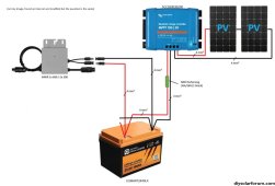
So, yeah, hook batteries direct to microinverters, it works fine. A battery is like a huge solar panel, at least for lithium batteries, a microinverter goofing around doing MPPT is not changing the voltage, it just runs at max output of the microinverter. Switch the AC side to control them individually, most any tiny relay can handle 240v AC at less than an amp, for these ~200w microinverters.

I have a new question: I just picked up a pair of 9s Leaf modules that I'd like to use, each with it's own BMS. I'm wondering about some sort of controllable (pwm, analog or serial data) DCDC converter that I could piggyback these 9s modules on the main inverter DC bus (as if it was a solar charge controller directly charging the FLA battery, which I used to do). Otherwise, need to set up more microinverters to discharge this pack, and either an AC to DC charger from excess solar. Anyone have ideas about how to make use of yet another voltage battery bank? Thanks!

1702006141604.png1702006201566.png1702006318195.png

Too many more pictures: https://photos.app.goo.gl/q1euFhioH266nPvW9
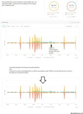
 
Last edited:
What is this particular PWM module that you speak of?

Oh I see now
 
Last edited:
Interesting overview of nighttime consumption of Enphase Microinverters (applicable to any inverter):
(no pun intended ;)), but at least it confirms that the 8 x 2700uF caps I see in my NEP 590W dual Microinverters are on the DC input.
Hah, Horrors! I thought they use a little power overnight, but I guess it's really mostly the Envoy using power overnight. I turn mine off at night! Since I made a contactor transfer switch for the main grid-tied array, I leave it off at night. Might save lifetime on the AC side capacitors having them turned off at night? Also prevents any lightning strikes from the grid getting into the array and microinverters, and prevents any lighting that hits the array from getting into the house, at least by L1,L2. No stopping N,G, but hopefully that's just going to ground. https://photos.app.goo.gl/UcDfekbC1J3qAJ6J9 If it's only the Envoy load, one could put a smart plug on it to turn off at night.

I have other microinverters on the off-grid side of the system, behind the main battery inverters, and those I leave on. The EEVblog video relieves me from the guilt of their extra load (he says no there's no extra load from the microinverters). In fact, maybe they're making it easier on my main battery inverters, but having the extra capacitance on the AC side. But copper losses though....
 
Last edited:
There are 3 broad architectures / circuits being pursued to power Microinverters from batteries in the recent posts of the thread:

DIRECT FROM BATTERY:

kundip has been running a direct from battery circuit for over 2 years now and the only real question we are trying to get a handle on is what effective round-trip resistance he has in that circuit and why he has had no issue with Resistance Check Fault conditions if others are unable to get a similar circuit working.

AGT also has a direct from battery circuit working but in his case, he is using a 4 Ohm inline resistance to pass the Resistance Check / MPPT Lock-on phase and switching from 4 Ohms to a 0.05 Ohms power resistor after power generation starts (and likely closer to 0.07 ohms all-in).
I have had a handful of times where the micros connected to the Electrak tractor have tripped the ground fault detection. Maybe this is what you call resistance check fault. The fault can be reset using the Envoy. The micros set the GFI maybe randomly, I have theories about why, or maybe I'm just doing certain dances to prevent it. The tractor is from the 70s and it from time to time does have a fault from DC+- to AC ground. The tractor's on-board charger has N,L1 going into the tractor, and the AC G is connected to the tractor chassis. So if the tractor and the 70's relay controls have any leakage between battery DC pos or neg to chassis and ground, the microinverters may notice and set the GFI.

If the mower deck is left plugged in, could be a cause, when the deck is turned off, the tractor shorts the motors to stop them rotating. Just a week or two, the off-board charger anderson connector came loose, and that tripped it. There are two chargers, one on each 120v leg, one in the tractor as original, and one on the shelf in the yellow box. From that off-board charger, there's a 30breaker feeding the micros to the left. There's a precharge lightbulb in the off-board charger, after plugging the tractor back in, wait for the bulb to go out before turning on the 30a breaker. Beyond connection & wire resistances, there is not any extra resistance between the batteries and the micro 'PV' input.
1702007037730.png
 
Last edited:
Also, while it didn’t produce AC, the final test case with no resistors did not trigger the "DC Resistance Low" error! More evidence suggesting my first two m250’s were duds somehow.
Plenty of old micros are duds. Make friends with a solar installer, they may have piles of them in the woods behind their house, and you just need to plug them in one by one and see if they work. I made several trips like the picture here. My limit was the hand truck capacity per trip.

Be careful testing them. Ground fault light on means the case of the micro could be PV or AC hot. I got a tingle once...

I don't recall finding any bad m190IG, or IQ. Just the older m190/210 style have had poor reliability. Of those, I've found roughly a third that still work correctly, plus others at a reduced power level of say 140w. I've kept those, but haven't tried putting them back in use yet. Every now and then, I check that the battery micros are still producing, I did replace one recently. 1702008206932.png
 
Last edited:

diy solar

diy solar
Back
Top