diy solar

diy solar

Van electrical update, 12v 10kwhh+, solar & alternator - Please review.

Aero

New Member
Joined
Mar 14, 2020
Messages
73
Hello everyone :)

I want to improve my wiring diagram.

1) Fuse sizing for each battery pack
The inverter is a Multiplus 12/3000/120
It's 3000VA, 2400W continous and 5500 peak.

According to my energy audit, max loads and the formulas I found on the forum and guides.
I took into account the inverter effiency for AC loads. 93%
1648326185184.png

I calculated 266 Amps divided by 3 battery pack. 89A max load per battery pack.
89 * 1.25 head room for the fuse = 111. The one just above is 125Amps.

2) Wire sizes for battery positive to fuse

For the wire size to fuse and positive post, I used the bluesea calculator. It suggest 4AWG wires. Up to 155Amps.

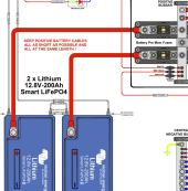
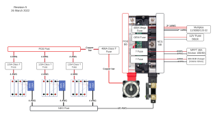
3) Wiring diagram
Any errors you can spot?

1648326014875.png
 
Your energy audit is very confusing. There should be a total watt hours per day somewhere otherwise it isn't useful.

Electric heat in a van is far from ideal. It's uses so much power. Why not something like a Webasto diesel heater?

You need to rethink how the parallel batteries are wired and fused. Your inverter can pull up to 300A from the batteries at full load. Each of your batteries have a 150A BMS so two of the three can handle the load. You need to wire in case 1 or 2 batteries fail and the remaining 1 or 2 are left to handle the load. I would wire each battery with 1AWG wire and use a 150A fuse. With that setup one battery can fail and the other two can keep going. If a 2nd fails while the inverter is at full load then the 3rd battery's fuse will pop due to the overload and the inverter will shutdown.

The 4/0AWG between the bus bars and main switch and shunt is good. Make sure the battery bus bars are rated for 500A since you have a 400A main battery fuse.

A 40A fuse for the 30A SCC. A 40A fuse for the 30A Orion.
 
That's a lot of class T fuses. Why not just do a traditional parallel wiring using short cables/lugs and only the single 400A T-class fuse? I'm sure it would be less expensive and just as effective. Also, to ensure balanced charging/discharging, wiring from batt1 pos and batt3 neg (or vice versa) to the Lynx is normally recommended when wired in parallel.
 
2 * 1 awg for the multiplus circuit is a bad idea.
If one wire becomes disconnected the other will very likely melt before the 400 amp fuse trips.
Suggest a single 4/0 awg wire instead.
I wonder why Victron specifies double wires.
From memory its 1/0 awg not 1 awg btw.

The smallest mega fuse Victron lists is 60 amps and the maximum fuse size the mppt solar charge controller specs is 40 amps.
Since the mppt has built-in short circuit protection its seems like more Victron doco silliness.
Also since the terminals can accept 16mm2(6 awg) wire I suggest...

6 awg and 100 amp fuse for the B2B charger
6 awg and 100 amp fuse for the mppt
6 awg and 100 amp fuse for the fuse block.

Consolidates the BOM and reduces the number of spares you have to keep on hand.
 
Last edited:
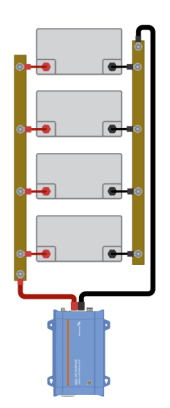
@Aero your diagram shows busbars but the label says post, if its actually a busbar you might consider attaching the main wires to oppposite ends in order to balance the path resistance across the batteries.
 
Thanks everyone for your answers :)
Your energy audit is very confusing. There should be a total watt hours per day somewhere otherwise it isn't useful.
Sorry for the confusion. Energy audit isn't the best term I agree.

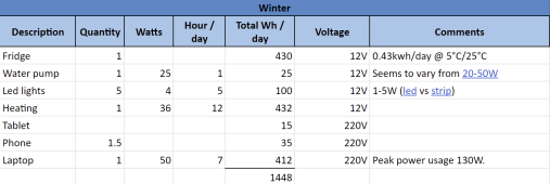
I did an energy audit at the beginning for the first version of my install.
1648499932896.png
But this time, I want to do things properly and I'm looking more into the biggest load and not the daily wh.

Electric heat in a van is far from ideal. It's uses so much power. Why not something like a Webasto diesel heater?
Agreed. I already have a webasto. It's not for day to day and permanent use. It's one of the infrequent use I have when I'm plugged to shore and would be able to still use when travelling. At some period of the year, it's warm enough to not warm the van for the day but too cold to take a shower when getting back to it in the evening or morning. So instead of warming the whole van, I use a small electric heater just to warm up the bathroom.

You need to wire in case 1 or 2 batteries fail and the remaining 1 or 2 are left to handle the load. I would wire each battery with 1AWG wire and use a 150A fuse. With that setup one battery can fail and the other two can keep going. If a 2nd fails while the inverter is at full load then the 3rd battery's fuse will pop due to the overload and the inverter will shutdown.
Smart idea!
 
That's a lot of class T fuses. Why not just do a traditional parallel wiring using short cables/lugs and only the single 400A T-class fuse?
My past readings on this forum gave me the impression that it was better to fuse each battery pack.
This topic for instance :

Also on Victron's forum (but refered to 2S2P config) : https://community.victronenergy.com/questions/31994/parallel-wiring-of-lifepo-batteries.html

And on their wiring examples, each battery is fused

1648501344053.png

I would need to read more about it.
 
Last edited:
2 * 1 awg for the multiplus circuit is a bad idea.
If one wire becomes disconnected the other will very likely melt before the 400 amp fuse trips.
Suggest a single 4/0 awg wire instead.
I wonder why Victron specifies double wires.

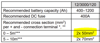
I read on some forums marine oriented that's it's not recommended. For safety and code reasons.
But then I saw Victron installation manual again and it states
1648501058260.png

I wondered if it was for an off grid usage, so looked again at their wiring examples.

The diagram contains an alternator and starter motor, so it's definetely a moving thing.
 
I read on some forums marine oriented that's it's not recommended. For safety and code reasons.
But then I saw Victron installation manual again and it states
View attachment 89033

I wondered if it was for an off grid usage, so looked again at their wiring examples.

The diagram contains an alternator and starter motor, so it's definetely a moving thing.
I saw that too and commented on it.
I think you should use 1x 4/0 awg and 400 amp fuse.

Oh I see its because the inverter/charge has double lugs.
I stand by 1x 4/0 awg and a 400 amp fuse.
 
I wonder why Victron specifies double wires.
It may be related to the lug size. Not sure if a 0/4 AWG fits.
The smallest mega fuse Victron lists is 60 amps and the maximum fuse size the mppt solar charge controller specs is 40 amps.
Since the mppt has built-in short circuit protection its seems like more Victron doco silliness.
Also since the terminals can accept 16mm2(6 awg) wire I suggest...

6 awg and 100 amp fuse for the B2B charger
6 awg and 100 amp fuse for the mppt
6 awg and 100 amp fuse for the fuse block.
I will have to check. I think in my first install, I put 60A for the MPPT.

Will also check for the fuse block.
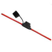
If I recall properly it has an OEM fuse on the line itself.
Something similar to
1648501894533.png
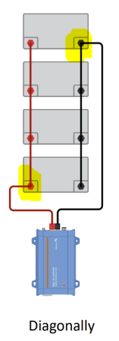
@Aero your diagram shows busbars but the label says post, if its actually a busbar you might consider attaching the main wires to oppposite ends in order to balance the path resistance across the batteries.
My thinking was that a post would probably be easier to mount space wise. Not sure if it's actually the case but the diagram show that my thinking was still in process. That's why the label says post and the diagram shows more of a busbar.

Good catch.
Like this right?
1648502030122.png

I had that in mind related to the diagonal wiring but didn't see it was also the case for busbars. Thanks!
1648502118966.png
 
It may be related to the lug size. Not sure if a 0/4 AWG fits.
Most people use 4/0 awg with these units.
From memory they have m8 studs.
I will have to check. I think in my first install, I put 60A for the MPPT.

Will also check for the fuse block.
If I recall properly it has an OEM fuse on the line itself.
Something similar to
View attachment 89042

My thinking was that a post would probably be easier to mount space wise. Not sure if it's actually the case but the diagram show that my thinking was still in process. That's why the label says post and the diagram shows more of a busbar.

Good catch.
Like this right?

If you aggregating to posts that is fine.
If you are aggregating to busbars they should be tapped at opposite ends.
 
So yours is on the left I guess, confirm?
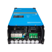
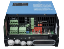
I'm not sure. On online pictures of my model, I see 1 stud positive, 1 stud negative.
But in the 230v manual, I see stated that there is 2 studs postitive and 2 studs negative.
 
After two many diagrams and pdf I probably looked at the wrong one indeed.
At the same time, they show a Multiplus diagram on the Multiplus2 product page...
 
@smoothJoey: what do you think about fusing each battery pack with it's own class T fuse and another additional 400A class T before the Lynx distributor?
 
@smoothJoey: what do you think about fusing each battery pack with it's own class T fuse and another additional 400A class T before the Lynx distributor?
Its best practice to fuse each lfp battery as close as possible to the battery positive terminal.
Depending on the ah rating of each battery you might get away with a lessor fuse.
What is the ah rating of each battery?
If you use a discrete fuse you can use a lynx_power_in instead of a distributor.

Actually you should consider using a power_in instead of a distributor.
You can fuse the branch circuits for fault isolation using this hack
and leave the battery circuits fused at source.
 
But this time, I want to do things properly and I'm looking more into the biggest load and not the daily wh.
To do it properly you need to know your daily Wh usage so you can properly size your battery and solar. Looking into the biggest loads is very useful too. It can help you to decide to avoid such loads as well as determine what size inverter you need.
 
Back
Top