diy solar

diy solar

Victron Smart Shunt - "correct" installation

bigmanonahill

New Member
Joined
Jan 6, 2021
Messages
18
Hello all, I hope this is the right place for this question...

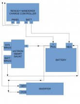
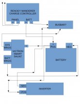
I purchased the Victron Smart Shunt and I'm not entirely certain how to correctly wire the Smart Shunt in this scenario.

I have a 100w Renogy kit with the 30A Wanderer controller, a battery, and an inverter.

I have included a diagram of what I *thought should be correct, however I read this in the Smart Shunt manual;

"there should be no other connections on the battery negative"

If that is the case, then the way it is wired in my diagram is wrong.

Can someone please clearly explain (or even better DRAW a DIAGRAM so my little brain can understand) exactly how to correctly wire this in?

Any help is most appreciated!
 

Attachments

  • solar1.jpg
    solar1.jpg
    49.8 KB · Views: 116
You'd usually have a negative busbar that one or two large cables from the shunt connects to and everything else connects to the busbar since you'd typically need to have multiple connections to the negative busbar.
 
Shunt sits between Battery Negative and all other connections to battery negative (ie System Minus).
That way it records all power to and from battery.
Shunt resistance is so low it should have no effect on performance.
 
Shunt sits between Battery Negative and all other connections to battery negative (ie System Minus).
That way it records all power to and from battery.
Shunt resistance is so low it should have no effect on performance.
Is this diagram correct then?
 

Attachments

  • solar2.jpg
    solar2.jpg
    54.4 KB · Views: 95
This is a good picture:

1610987124652.jpeg

Please note how the current needs to flow through the shunt by basically cutting the thick cable out of the battery negative, crimping two lugs on the wire you just cut. In my case the were 4/0 to 5/16” lugs. Put the Pos supply cable in the shunt, and then attach the lug to the positive battery post. Plug the cable from the shunt to the battery monitor and THat is all you need to do to monitor a battery.

The cable plugging into the shunt at B1 and B2 with a dotted line is an accessory, which is not needed. The one pictured is for a second battery system, IMO not necessary. I did urchase a battery temp sensor which plugs into B1 B2.

One of my lessons learned is lug sizing and space. Making thick cables for 5/16 posts takes up a lot more room than I expected compared to some of the 14 gauge wire with #10 lugs I’d crimped for fuse boxes before. Those thick battery cables do not, and should not be bent into the sharp 90 degree angles in the pic.

For nothing else before the shunt, that means don’t put a load before it, and don’t put a battery fuse before it.
 
This is a good picture:

View attachment 33646

Please note how the current needs to flow through the shunt by basically cutting the thick cable out of the battery negative, crimping two lugs on the wire you just cut. In my case the were 4/0 to 5/16” lugs. Put the Pos supply cable in the shunt, and then attach the lug to the positive battery post. Plug the cable from the shunt to the battery monitor and THat is all you need to do to monitor a battery.

The cable plugging into the shunt at B1 and B2 with a dotted line is an accessory, which is not needed. The one pictured is for a second battery system, IMO not necessary. I did urchase a battery temp sensor which plugs into B1 B2.

One of my lessons learned is lug sizing and space. Making thick cables for 5/16 posts takes up a lot more room than I expected compared to some of the 14 gauge wire with #10 lugs I’d crimped for fuse boxes before. Those thick battery cables do not, and should not be bent into the sharp 90 degree angles in the pic.

For nothing else before the shunt, that means don’t put a load before it, and don’t put a battery fuse before it.

good enough. depending on inverter power draw, i would connect it directly to the shunt
I'm still lost I guess. Thanks for the above diagram but that does not show where the controller/other negative connections fit in. Pappion, if I connect directly to the inverter then where does the controller get a negative connection?
 
I have my positive battery cable going to an 8 post bus bar to distribute as needed. I have the negative cable going to an 8 post bus bar also.

In case, both positive and negative is:

1) Battery
2) Solar Charge Controller # 1
3) Solar Charge Controller # 2
4) Solar Charge Controller # 3
5) Inverter
6) RV 12 volt Power
7) USB Charger circuit
8) Empty for Future expansion.

Specifically, I bought two of these bus bars are Blue Sea 8 Post 3/8 stud https://www.waytekwire.com/item/78259/Blue-Sea-Systems-2107-PowerBar-BusBar/

Done, over, I would still get 8 studs, but not buy an eight 3/8 studs. I would also get a covered busbar.
 
  • Like
Reactions: JRH
I'm still lost I guess. Thanks for the above diagram but that does not show where the controller/other negative connections fit in. Pappion, if I connect directly to the inverter then where does the controller get a negative connection?
You can have two connectors on Shunt terminal. I would not do 3. I use a 6 post 5/16 bus bar for solar and system ground.
I have smaller bus bars for +12v, and a switch to select solar, trailer, or both.
 
You can have two connectors on Shunt terminal. I would not do 3. I use a 6 post 5/16 bus bar for solar and system ground.
I have smaller bus bars for +12v, and a switch to select solar, trailer, or both.
Not according to this from the Victron Smart Shunt manual; "there should be no other connections on the “BATTERY MINUS” connection of the SmartShunt. And similarly, there should be no other connections on the battery negative. Any loads or chargers here will not be included in the battery state of charge calculation."

So I guess I'm going to return this device or sell it if I can't, because apparently I'm not smart enough to install the smart shunt...which is too bad because the features are exactly what I was hoping to have.
 
You'd usually have a negative busbar that one or two large cables from the shunt connects to and everything else connects to the busbar since you'd typically need to have multiple connections to the negative busbar.
Before I completely throw in the towel, I really think this is the main area of my misunderstanding...the busbar function. What exactly is the difference between using a busbar/distrubution block and stacking multiple connections on the shunt terminals?
 
The busbar connects other things side by side instead of stacked.

Should be a lower resistance connection although I have certainly stacked two (and won’t publicly admit to 3) connections.
 
I umm....... I have a friend who did it like this:
 

Attachments

  • B6C3AEE5-C13E-4C35-91B1-4E0FBE7460CD.jpeg
    B6C3AEE5-C13E-4C35-91B1-4E0FBE7460CD.jpeg
    119 KB · Views: 128
Although the shunt should be directly on the negative terminal a piece of copper busbar was needed to make it work physically.

And he felt the two very low amp connections would be alright stacked on top of the main connection to his inverter.
 
I umm....... I have a friend who did it like this:
hehehehe...thanks to your friend for his pic. But seriously what about the statement "Any loads or chargers here will not be included in the battery state of charge calculation"....are you sure whatever you have stacked there is actually being reflected in the state of charge calculation? How can you tell?
 
The actual shunt is a stupid simple monitoring device.

No current can leave the battery without traversing the shunt in that picture.

As long as ALL current traverses the shunt it will be measured. It’s just that simple ?
 
The busbar connects other things side by side instead of stacked.

Should be a lower resistance connection although I have certainly stacked two (and won’t publicly admit to 3) connections.
The actual shunt is a stupid simple monitoring device.

No current can leave the battery without traversing the shunt in that picture.

As long as ALL current traverses the shunt it will be measured. It’s just that simple ?
So then there is NO FUNCTIONAL difference between stacking connections on the system minus terminal as shown in your pic and using an external busbar/distribution device for the negative system connections....?
 
Not according to this from the Victron Smart Shunt manual; "there should be no other connections on the “BATTERY MINUS” connection of the SmartShunt. And similarly, there should be no other connections on the battery negative. Any loads or chargers here will not be included in the battery state of charge calculation."

So I guess I'm going to return this device or sell it if I can't, because apparently I'm not smart enough to install the smart shunt...which is too bad because the features are exactly what I was hoping to have.

All current needs to go through the shunt. Nothing but battery connected to "battery minus" connection of shunt. Everything connected to other side of shunt, whether stacked ring terminals or through a busbar.

The shunt ought to do what you need.

So then there is NO FUNCTIONAL difference between stacking connections on the system minus terminal as shown in your pic and using an external busbar/distribution device for the negative system connections....?

Correct.
 
The only functional difference is a slight increase in resistance due to the stacked connections. IF that occurs there will be some heat generated which will of course be wasted energy. However, it will still be measured by the shunt since it is on the output side. My friend assures me there is no heat generated.

Perhaps this is of some help:


The four wire metal shunt described is like the Victron.
 
Back
Top