diy solar

diy solar

Victron System with EG4 rack Mount

dab1294

New Member
Joined
Aug 21, 2022
Messages
24
So I am working on designing my first system. The project is an off-grid 17ft camper in AZ, just south of the Grand Canyon. Here is a photo of what I have come up with so far, but I do have a lot of questions.
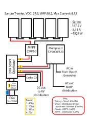
SolarDiagram.jpg

So here are my questions:
  1. What wire sizes/fuses should I be using for this system. I think I have a rough idea but with this being my first system I want to be sure.
  2. I want this project to be scalable if needed. Could I add another 5-panel series (5s2p) and another 400 amp-hour battery without having to change anything else in the system?
  3. How should this system be grounded? Do each of the components have an equipment ground?
  4. If the EG4 has a breaker on the front, is a main fuse and battery disconnect still necessary?
  5. Can DC power be wired directly from the Lynx distributer to the DC distribution in my camper?
  6. Is the Cerbo necesary? What is the most cost-effective way for me to be able to monitor this system, preferably from off site? We will have Starlink, and I plan on setting it up to have back up power available totally separate from the system.
  7. Is a disconnect between the panels and MPPT recommended? Should there be a fuse in between those as well?
 
I'm already realizing that charge controller should probably be a 250/100. Meaning the wire from it to the distributer should be 2 AWG.. I think.
 
3000VA ~= 2400 watts
2400 ac watts /.85 conversion factor / 12 volts low cutoff = 235.294117647 service amps
235.294117647 service amps / .8 fuse headroom = 294.117647059 fault amps

You should have a means of disconnect between the pv string and the solar charge controller.
The max continuous discharge rate for you eg4 battery is 200 amps, the inverter alone can far exceed that.
Victron doesn't make a 315 amp mega fuse and they call for a 400 amp fuse for the inverter circuit
Suggest to connect the cerbo to an empty position in the rv distribution panel, that way its on a fused circuit.
The lynx shunt is really expensive and only really makes sense if connected between lynx components.
I suggest you save some bucks with a Victron Smartshunt instead.
 
I'm already realizing that charge controller should probably be a 250/100. Meaning the wire from it to the distributer should be 2 AWG.. I think.
Assuming pure copper wire with insulation rated to 105C.
6 awg is good for 100 fault amps and 70 service amps.
4 awg is good for 150 fault amps and 120 service amps.

I suggest that you upgrade the mppt and rv distribution circuits to 4 awg with 150 amp fuses
 
Is this a 50A rv?
Here is my version based off yours.
Suggest you use a lynx power-in instead of a lynx distributor and use this video to fuse the 3 of the 4 branch circuits.

This attached text file describes all the connections.
The legend block describes all the atoms included in the dc_domain block.

UPDATE: fix thinko in drawing.
 

Attachments

  • dab1294.txt
    1.2 KB · Views: 13
Last edited:
You should have a means of disconnect between the pv string and the solar charge controller.
Thats what I figuredWould I need fuses in that circuit anywhere?
The max continuous discharge rate for you eg4 battery is 200 amps, the inverter alone can far exceed that.
Would this cause any issues other than limiting me to 200 amps? I am not expecting to ever need more than that for our project.
Victron doesn't make a 315 amp mega fuse and they call for a 400 amp fuse for the inverter circuit
Awesome, I'm sure I would have been scratching my head looking for one.
Suggest to connect the cerbo to an empty position in the rv distribution panel, that way its on a fused circuit.
I believe the Cerbo comes with a fused line to connect to the distributer.
The lynx shunt is really expensive and only really makes sense if connected between lynx components.
This makes sense too. If I went with the smart shunt, I'd just need to add a main fuse between the battery and smart shunt then, correct?
I suggest that you upgrade the mppt and rv distribution circuits to 4 awg with 150 amp fuses
Thank you! I may do 2 awg anyway because I think I have some of that already.

Thank you for all the advice!
 
Thats what I figuredWould I need fuses in that circuit anywhere?
You don't need over-current protection on a single string.
But the means of disconnect is very useful to isolated your charge source.
Would this cause any issues other than limiting me to 200 amps? I am not expecting to ever need more than that for our project.
Its my policy to always design for the maximum continuous capacity of the inverter.
I design the system not for the diyer but for the diyer's teenage son or daughter. :)
In my imagination they are good kids but they don't think about where the power comes from.
Awesome, I'm sure I would have been scratching my head looking for one.
If you have any questions I glad to answer.
I believe the Cerbo comes with a fused line to connect to the distributer.
True, but there is a concept called "selective coordination".
What it means is that based on the feeder dead short ampacity there is a safe minimum wire size for the first level of branches.
For the lynx products its ~6 awg based on a minium fuse size of 60amps.
This makes sense too. If I went with the smart shunt, I'd just need to add a main fuse between the battery and smart shunt then, correct?
Correct.
Thank you! I may do 2 awg anyway because I think I have some of that already.
Then you can use 200 amp fuses.
The lugs in the rv distribution center probably won't land 2 awg though.
Thank you for all the advice!
You are welcome.
 
Is this a 50A rv?
Here is my version based off yours.
Suggest you use a lynx power-in instead of a lynx distributor and use this video to fuse the 3 of the 4 branch circuits.

This attached text file describes all the connections.
The legend block describes all the atoms included in the dc_domain block.
I've never seen anything written out like this, so I'm going to have to stare at it for a while before it clicks, but thank you for putting in the work! I really appreciate how helpful everyone here is.
Its my policy to always design for the maximum continuous capacity of the inverter.
So for a total newbie like me, what would happen if the demand from the inverter exceed the max discharge rate of the battery. Does the batter just become a bottleneck? Or does discharge increase and damage something? Or does everything just shut down?

In theory, my maximum power draw would be ~2.5kw hours if we were running everything at once AND had multiple devices charging.
 
Have you run the VictronConnect mppt calculator with the temp coefficient of the panels? VOC can rise significantly above nameplate in the cold.

For thinking about additional strings of panels you need to think about the amps between the MPPT at 12v. Your 1500w solar converted to 12v is already 125amps. So wire and fuse 4 need to be bigger. If you were going to add a second parallel string then you’d be looking at 250amps through that connection. Second MPPT is always an option (although space on the bus bar is limited).

Have you considered 24v? Makes wire sizes and amperage much more manageable. Almost all RV 12v stuff can run at 24v, but need to check it all, can replace the few things that don’t run at 24v. So you dont necessarily need a 12-25 dc-dc converter.

I think you’ll love the Cerbo GX, especially with Starlink. Annoyingly Starlink is AC power only so the inverter will need to be in all the time.
 
I've never seen anything written out like this, so I'm going to have to stare at it for a while before it clicks, but thank you for putting in the work! I really appreciate how helpful everyone here is.

So for a total newbie like me, what would happen if the demand from the inverter exceed the max discharge rate of the battery. Does the batter just become a bottleneck? Or does discharge increase and damage something? Or does everything just shut down?

In theory, my maximum power draw would be ~2.5kw hours if we were running everything at once AND had multiple devices charging.
The BMS will like be the first thing to trip on over-current.
If the BMS fails then either a branch fuse or battery breaker will pop.
 
Last edited:
Almost all RV 12v stuff can run at 24v, but need to check it all, can replace the few things that don’t run at 24v.
I'm skeptical of your claim.
Although I like the idea of doing a 24 volts core with a buck converter to power the legacy rv stuff.
 
@dab1294 the heart of the system is the busbars.
The systems we make look like a ladder where the risers are the busbars a the rungs are the circuits.
The busbars are the top level opjects in the dc_domain.
 
Last edited:
@dab1294 a FET based BMS disconnecting at >200 amps is a brutal event for the transistors in the BMS.
FETs have a habit of failing closed and its usually not detected until the next event when your batteries are destroyed when the BMS fails to protect them.
 
For thinking about additional strings of panels you need to think about the amps between the MPPT at 12v. Your 1500w solar converted to 12v is already 125amps. So wire and fuse 4 need to be bigger. If you were going to add a second parallel string then you’d be looking at 250amps through that connection. Second MPPT is always an option (although space on the bus bar is limited).
I realized this after. Seems like if I was going to add another series a second MPPT would make the most sense.
Have you considered 24v? Makes wire sizes and amperage much more manageable. Almost all RV 12v stuff can run at 24v, but need to check it all, can replace the few things that don’t run at 24v. So you dont necessarily need a 12-25 dc-dc converter.
I hadn't really. I considered a 48v system with the EG4 AIO aby the EG4 48v battery, but have had so many people tell me that if I want reliability, Victron is the way to go. Any suggestion for what a 24v system would look like?
Annoyingly Starlink is AC power only so the inverter will need to be in all the time.
This is why I was considering building another mini system with something like a Ecoflow or Jackery. Have that plugged in to the main system, but also give it its own solar input, so if the main system has an issue, Starlink won't lose power immediately.
 
@dab1294 a FET based BMS disconnecting at >200 amps is a brutal event for the transistors in the BMS.
FETs have a habit of failing closed and its usually not detected until the next event when your batteries are destroyed when the BMS fails to protect them.
So what is the solution to that problem? Is max discharge additive? If I add a second battery does that solve the problem?
 
I'm skeptical of your claim.
Although I like the idea of doing a 24 volts core with a buck converter to power the legacy rv stuff.
Yeah, I'm skeptical of that claim as well :)

But I haven't found anything in my RV that it isn't true for, everything I look at says 12-24v (lights, usb chargers) That said, I removed the absorption fridge and I haven't checked the tongue jack. I have the trailer brakes connected to a completely separate 12v system, so those are probably 12v only.

Anyway, fair point, it would take a lot of checking and a 24-12v converter is pretty inexpensive insurance :)
Wfco panels are supported for 24 volts nominal.
 
I realized this after. Seems like if I was going to add another series a second MPPT would make the most sense.

I hadn't really. I considered a 48v system with the EG4 AIO aby the EG4 48v battery, but have had so many people tell me that if I want reliability, Victron is the way to go. Any suggestion for what a 24v system would look like?

This is why I was considering building another mini system with something like a Ecoflow or Jackery. Have that plugged in to the main system, but also give it its own solar input, so if the main system has an issue, Starlink won't lose power immediately.
A 24v system would look basically the same, with three main differences:

- Need to get a 24v Victron inverter/charger (24/2000/50 or 24/3000/70)
- have the battery at 24v (either directly or 12v wired in series). eg4 make an equivalent battery wired to 24v. https://signaturesolar.com/eg4-lifepower4-lithium-battery-24v-200ah/
- Add an Orion 24-12v converter between the busbar and the RV 12v system.

Same type of fuses (smaller amp needed), same disconnects, wire a lot smaller due to halving the amps.
 
Back
Top