CaliSunHarvester
Solar Enthusiast
Posting this as I was hijacking someone's thread where the temperature coefficient was mentioned.
In my ~2 week old installation I apparently run the risk of sending too high voltage to the charge controller. I consider myself very lucky reading the other thread and catching the temperature issue there (it was barely mentioned until I hijacked it).
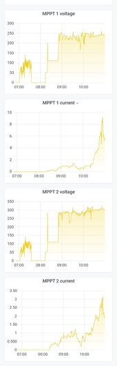
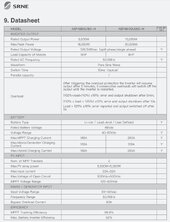
Inverter charger is a Sungoldpower 10kW with Voc.max of 500V
Panels are REC 260 with Voc of 37.8V
I put 13 panels on string.. 13 x 37.8 = 491.4V
Which is under 500V
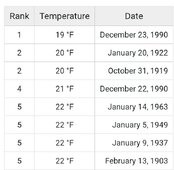
But now I learn that these panels' Voc increases by 0.25% for every degree Celsius dropped.
Inverter hasn't thrown a fault code in 2 weeks of operation.
In my ~2 week old installation I apparently run the risk of sending too high voltage to the charge controller. I consider myself very lucky reading the other thread and catching the temperature issue there (it was barely mentioned until I hijacked it).
Inverter charger is a Sungoldpower 10kW with Voc.max of 500V
Panels are REC 260 with Voc of 37.8V
I put 13 panels on string.. 13 x 37.8 = 491.4V
Which is under 500V
But now I learn that these panels' Voc increases by 0.25% for every degree Celsius dropped.
Inverter hasn't thrown a fault code in 2 weeks of operation.