diy solar

diy solar

Voltage Between Grounded Ladder and Roof

TurbineTester

New Member
Joined
Apr 1, 2021
Messages
143
I just a had a weird experience. We recently installed 36 panels on two different roofs. Main house (27) and Garage (9). have two EG4 6500EX inverters in the garage powering a sub panel in the garage for now. These two inverters are not playing well with each other in split phase mode (https://diysolarforum.com/threads/eg4-6500-power-output-problem.43408/page-3#post-644580). So i just ran one inverter in single phase mode. I have my son installing gutter guards on the gutters and he had been having the ladder on the concrete. But he moved it so the feet were in the flower bed between the house and garage and said he "felt a tingle" when he got to the top of the ladder and was touching the roof. So i got up there with my volt meter and sure enough there was about ~177v AC potential between the ladder and the roof. I checked for DC potential as well and found nothing. When i turned the inverters off, the votage went away. I can see no possible way that i have a short between any AC output and the roof of my garage. It's a metal roof but vinyl siding and wood framing on concrete slab. The only way the roof itself is grounded is through the gutter downspouts. All the inverter output goes directly to the sub panel where the NG is bonded in the panel as far as i can tell. There is one 10ga wire run from my main panel to the sub panel in the garage that is wired into the same panel as the inverter but it is on a separate breaker that is not energized currently. I only have this as a way to power the garage until we get the split phase problem sorted out with the EX inverters . However that 10ga wire from the house has neutral and ground connected in the sub panel, if that is relevant. So the NG from the house is bonded to all NG in the subpanel, even when the breaker in the subpanel is off. My main electrical service is grounded within 10 feet of this subpanel, and the main service panel in my house is less than 10' from the ground rods. The 10ga wire from the main panel to the garage is 4 conductors, L1 L2 N G. When i disconnect athe N and G from the sub panel the voltage on the roof goes down from ~177 to around 60V. When either the N or G of the 10ga wire is connected back to the sub panel the voltage goes back to 177. If i disconnected the PV array from the Inverter the voltage goes to 0ish (1-5v). If i leave the PV array connected but put the interver in standby the voltage goes to 0 (1-5V). At this point i'm measuring the voltage by putting the negative probe of my Klein MM in the wet dirt and the postive probe on the gutter down spout. I don't know that any of this other information is relevant at this time but i'm trying to figure out hwo the heck i'm getting live voltage on my metal roof. Any help is appreciated.
 
All the above testing was done with the array on the garage roof connected to Inverter 2. I jsut did some testing with the arrays on the main roof and inverter 2. With no NG connection from the 10ga wire from the main panel in the sub panel, PV disconnected there is <1v from ground to roof. With Inverter on and PV connected there is about 14v. With the PV connected and the NG connected in the subpanel there is about 44v on the roof. Again, hope someone can steer me in the right troublshooting direction here. Thanks in advance.
 
Are finding if you disconnect the NG bond the AC voltage on the roof goes down or completed disappears?
 
Are finding if you disconnect the NG bond the AC voltage on the roof goes down or completed disappears?
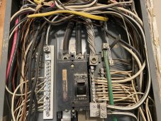
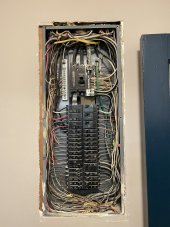
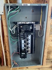
There is no way for me to separate the NG bond in the sub panel without attaching a separate ground bar. Also, i actually took the cover off my main panel and there is no NG Bond in the main panel. The NG do show continuity in the main panel, thus i suspect that the meter base grounding is bonded to N. I'll post pictures of both panels in a minute.
 
Pics
 

Attachments

  • 1A5414E3-D2CB-4A71-BBBA-2CEF10F21E81.jpeg
    1A5414E3-D2CB-4A71-BBBA-2CEF10F21E81.jpeg
    399.1 KB · Views: 37
  • EAB21375-951B-49C0-BE0E-F690F8BDAA33.jpeg
    EAB21375-951B-49C0-BE0E-F690F8BDAA33.jpeg
    180.3 KB · Views: 37
  • 95CEA135-B918-4958-81A1-5578F2B2A560.jpeg
    95CEA135-B918-4958-81A1-5578F2B2A560.jpeg
    210.2 KB · Views: 37
Picture 3 is a subpanel?

That's all wrong, the panel needs a ground bar and all grounds separated. Any neutral current on there is paralleling on the ground.

Unless I'm missing an off grid or critical load panel special case.
Ok I used the term sub panel but that is incorrect, as it is currently set up as a main panel, not being fed from the main panel in my house. My configuration is consistent with Will’s in his video here at around the 10:30 mark
 
Ok I used the term sub panel but that is incorrect, as it is currently set up as a main panel, not being fed from the main panel in my house. My configuration is consistent with Will’s in his video here at around the 10:30 mark
Comment rescinded then, and I don't have the knowledge to comment further then.
 
So i got up there with my volt meter and sure enough there was about ~177v AC potential between the ladder and the roof. I checked for DC potential as well and found nothing. When i turned the inverters off, the votage went away.

And that, ladies and gentlemen, is why PV frames must be grounded. Back to chassis ground of PV equipment, to electrical boxes, to ground rod.

Even if there is no DC leakage, there is capacitive coupling of AC from PV to frame, and some inverters are transformerless and an AC signal rides on DC as common mode. Another guy here finally figured out why his poor dog didn't like to climb steps into his RV; when wired to ground mount PV array a similar thing happened.

Neutral/Ground bonding should also be done correctly. But biggest issue sounds like isolated frame of PV.
 
Yes, if an AC voltage is present on PV wires.
Normally for a grid-tie inverter (what I use) on 120/240V split-phase I would expect little voltage.
If I used the inverter for 208V across L1/L2 of the L1/L2/L3/N 120/208Y, I expect 60Vrms common mode.
I'm not sure what the off-grid inverters are doing that causes this problem.

If you had an appliance with 120V 3-wire plug and you put it in a 2-wire adapter, there might be some voltage present on ground pin. EMI filters have discrete capacitors to ground. Motor windings have parasitic capacitance. PV panels have parasitic capacitance.

Usually this capacitance, at 120V and 60 Hz, only creates 0.3 mA to 3 mA of leakage current. Enough to feel but not particularly dangerous.

A capacitor has an "impedance" (AC resistance) and your body has a resistance, so some current flows.

Grounding the chassis provide very low impedance (maybe 0.1 ohms) back to equipment, so any current generated flows through ground wire and voltage drops to about 0.0V
 
So as a layman let me see if I understand...
Voltage can be induced into the panel frame via "capacitive coupling"?
It is the capacitors in the inverter that are coupling to the ground. Internally the unit likely also couples the PV to ground via the MPPT circuitry. Usually there is very low energy; if you ground the array to the flower bed you will likely only see 0.1-3mA if current flowing.
 
And that, ladies and gentlemen, is why PV frames must be grounded. Back to chassis ground of PV equipment, to electrical boxes, to ground rod.

Even if there is no DC leakage, there is capacitive coupling of AC from PV to frame, and some inverters are transformerless and an AC signal rides on DC as common mode. Another guy here finally figured out why his poor dog didn't like to climb steps into his RV; when wired to ground mount PV array a similar thing happened.

Neutral/Ground bonding should also be done correctly. But biggest issue sounds like isolated frame of PV.
Thank you so much for the knowledge and expertise you are bringing to the tabel here. Ok so in my case all my panel frames are electricallly connected to my metal roof because of the metal clamps and screws etc. So if i ground the frames i will by default ground the roof, and i should also tie all the inverter and panel box frames to the same ground? Do i need to drive a separate ground rod or coudl i tie to the ground rods at the meter base? That meter base ground rod is between my house and garage and less than 10' from both panels and all the inverter boxes.
 
Internally the unit likely also couples the PV to ground via the MPPT circuitry.
Just to be clear, this means AIO.pv.negative is bonded to AIO.chassis and by extension AIO.ac.ground internally?
 
Last edited:
So if i ground the frames i will by default ground the roof, and i should also tie all the inverter and panel box frames to the same ground? Do i need to drive a separate ground rod or coudl i tie to the ground rods at the meter base? That meter base ground rod is between my house and garage and less than 10' from both panels and all the inverter boxes.

All metal objects should be connected by copper wire, even if in separate buildings. Because you have DC and/or AC power routed between the buildings.

A single ground rod (or network of rods, pipes, foundation steel) at meter panel takes care of most things. Some people say a second rod elsewhere is a problem in case of lightning strike nearby, some current would be diverted through your wires. But code may require it. I have two buildings 100' apart and ground rods at both also bonded to pipes etc. I like the idea that dirt I'm standing on is at same voltage as metal things I touch.
 
If you have a DC voltage between your panel frames and ground then you either have voltage leaking from a faulty panel or a faulty mppt circuit in the inverter.
As you seem to have an AC voltage and are already concerned about the state of health of one of your inverters maybe try swapping inverters first.
Most of the rest of the world insist that anything electronic in a metal case is connected to each other and ground.
Our weird split phase neutral grounded system looks worse the older it gets but we have backed ourselves into a corner with it and will have to make do.
 
OK, i've rigged some temporary wires and connected the main roof (and thus PV frames) to the main ground rod and the garage roof to a fence post and that has solved the "tingly roof" problem. Am i correct in assuming that the AC OUT ground connection on the inverters is connnected to the inverter cases? The two inverters are connected to ground through the AC out ground wire connecting to the NG bars in the garage panel and the NG wires from the 10ga wire that goes back to the main house panel and from there to the meter ground rod. It is kind of a long path to earth ground but it's there. I'll take a trip to the hardware store in the next day or two to get enough bare coopper wire to connect to the three PV strings on the main roof and bond that system directly to the meter base ground rod. From here i might have a problem...I need another bare copper wire from the frames of the garage roof PV string to another ground rod, but this give me two ground rods within 10' of each other, unless i put it on the opposite isde of the garage, and then it's still within 40'. So how do i permanently ground the garage PV string/roof without running into lightning strike problems? Since all the inverters are in the garage, should i connect them all to that new ground rod? For now this also seems to have solved the other problem of the 2p2 inverter voltage fluctuation. I watched the voltage for 5 minutes and both were rock solid at 120v.
 
Back
Top