diy solar

diy solar

What BMS uses inductive balancing?

burgerking

New Member
Joined
Apr 6, 2022
Messages
368
Location
Subic, Philippines
Most BMS uses resistors to bleed current for passive balancing.
A few uses capacitors to transfer charges for active balancing.

Any BMS that uses inductors (transformer) for active balancing?
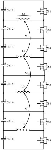
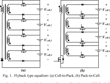
There are two types of inductor balancing:
1651132890104.png 1651132940383.png
Buck/Boost (Left) and Transformer (right) type

I am curious if this is more effective than Capacitor Balancer as this can transfer charges from multiple cells and into multiple cells at the same time.
 
Last edited:
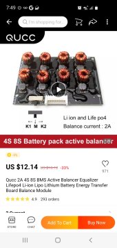
Screenshot_20220504-074916_AliExpress.jpg
If I'm not mistaken, it would appear that this uses inductors.
 
Has anyone got long term experience with these transformer balancers. I’ve seen too many failures with capacitor based balancers to leave them connected to a pack full time.

One of my cell suppliers has developed a transformer based active balancer to improve the reliability aspect.

I’d be keen to hear from anyone that has been using one for more than 5 years.
 
JK active balancer BMS is effectively an inductive balancer. It uses a buck DC-DC switcher to charge the super caps and a boost DC-DC switcher to recover stored supercap energy to push current to lowest voltage cell. Supercaps are in parallel and are about 2.5vdc once charged up. Only one 'from' and one 'to' cell at a time occurs during balancing. There are a bunch of 8 pin MOSFET's switches to do the selection multiplexing between the 'from' and 'to' cells.

I don't particularly like the use of supercaps, especially located near the heat generated from series pass MOSFET's of BMS.

I am curious if anyone has evaluated these active balancers.
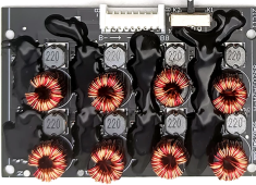
Qucc-2A-4S-8S-BMS-Active-Balancer-Equalizer-Lifepo4-Li-ion-Lipo-Lithium-Battery-Energy-Transfe...png

I believe they are using MT3608 2A boost switcher IC.

A similar 6 to 12 amp active balancer could be made with XR2981 boost switcher IC.

Stay away from these.
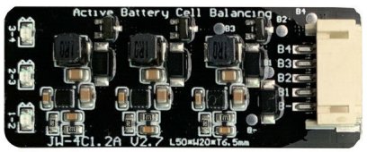
4 cell bms s-l1600.jpg
They are leap frog switcher based on ETA3000 IC which have a problem with cell voltage sensing due to the multiple IC's running asynchronously causing wiring voltage drop that interferes with the neighbor IC cell voltage sensing.
 
Last edited:
JK active balancer BMS is effectively an inductive balancer. It uses a buck DC-DC switcher to charge the super caps and a boost DC-DC switcher to recover stored supercap energy to push current to lowest voltage cell. Supercaps are in parallel and are about 2.5vdc once charged up. Only one 'from' and one 'to' cell at a time occurs during balancing. There are a bunch of 8 pin MOSFET's switches to do the selection multiplexing between the 'from' and 'to' cells.

I don't particularly like the use of supercaps, especially located near the heat generated from series pass MOSFET's of BMS.

I am curious if anyone has evaluated these active balancers.
View attachment 131287

I believe they are using MT3608 2A boost switcher IC.

A similar 6 to 12 amp active balancer could be made with XR2981 boost switcher IC.

Stay away from these.
View attachment 131298
They are leap frog switcher based on ETA3000 IC which have a problem with cell voltage sensing due to the multiple IC's running asynchronously causing wiring voltage drop that interferes with the neighbor IC cell voltage sensing.
I’ve attached a (poor) picture of the one I’m looking at.

I’m more concerned with reliability than anything, I’ve seen too many active balancer failures - some of which destroy cells.
 

Attachments

  • BDA10157-020C-4279-A819-BF08D8124AAB.jpeg
    BDA10157-020C-4279-A819-BF08D8124AAB.jpeg
    7.7 KB · Views: 16
I’ve attached a (poor) picture of the one I’m looking at.

I’m more concerned with reliability than anything, I’ve seen too many active balancer failures - some of which destroy cells.
I believe this one's balancing current is a function of how much voltage imbalance is. Like the capacitor balancers.
 
I believe this one's balancing current is a function of how much voltage imbalance is. Like the capacitor balancers.
That is how the supplier is saying it works. I know it works well, I’m concerned about the long term reliability if left permanently connected.

Thanks.
 
Has anyone got long term experience with these transformer balancers. I’ve seen too many failures with capacitor based balancers to leave them connected to a pack full time.

One of my cell suppliers has developed a transformer based active balancer to improve the reliability aspect.

I’d be keen to hear from anyone that has been using one for more than 5 years.
Not more than five years, have a long term (rather slow) development project here that I have been working on for a fair while.
Its the second circuit (a) in the first post. Preliminary testing with only a couple of cells looks very encouraging.
I bought a whole bunch of Chinese mosfet gate driver chips that were complete duds for my thirty cell balancer, to work on over Christmas, and that has set me back.

An internet buddy (in a different state) is following progress closely, has made himself some boards to my design and seems pretty happy with how its all going with his sixteen large cells.
Still very early days for him too, but it sure shifts some serious power between larger cells, which was the whole purpose of the exercise.

The secret to all this is to have a very low impedance between cells, so that a relatively high current can be transferred where there is a very low voltage differential. Capacitor balancers are a complete waste of time, it requires MASSIVE capacitance to transfer even a piddling amount of charge where the potential difference between cells is down in the millivolt range.

A very low impedance transformer, for instance a single turn on a fairly large toroid with super thick wire can be made to have an extremely low impedance without any difficulty at all.
Looking at it as an engineer, its really the only thing that is likely to work with really large cells.
The commercial units are a not very funny joke, and the claims made for what they are selling is laughable from what I have seen.

Its far too early to present this as an open source home brew project, but its coming....
I’m not interested in moving more than a few amps between cells as my system ramps down current in the balancing phase.

At this stage resistive balancing is fine, but the cells are 11 years old, and I want to be ready if they start to diverge more than the passive can handle.

I’ll follow your balancer progress with interest. Cheers.
 
No balancer is realistically going to shift several amps where the voltage differentials are really small.
Think about it.
Suppose you have 100 milliohms of impedance in your balancer, and one cell is 50mV higher than another cell.
If you are lucky you get 500mA of balance current.

Half an amp is not a lot, but if you have 300 amp hour cells it still takes a fair while.

Now suppose your balancer has only ten milliohms impedance between cells, a 50mV difference would shift five amps, and a 5mV difference 500mA.
That would be quite difficult to do, but its possible to build a transformer balancer, a hundred milliohms is dead easy, and ten milliohms would take a supreme effort. Most of that impedance is in just the cell to cell wiring.

The real aim is not huge current, but meaningful current once the cells are all getting pretty close.
You want to see something measurable happening in a day, not over a whole month.

The skinny cell wires on the commercial "many" amp advertised balancers is a total joke.
It might only be possible to reach the advertised amps, if the cells were maybe a whole volt different, which I hope never actually happens.

A more realistic specification would be balance current between cells at a 50mV difference.
But the commercial suppliers would never dare give a figure like that, it would be pitifully low.
"Five amp balancer" sounds so much better.
 
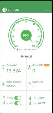
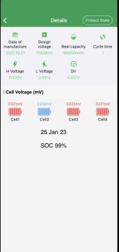
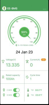
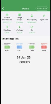
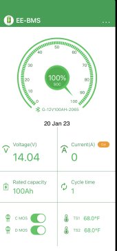
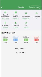
Are these cell balances a product of the bms or just a natural process of the interconnected cells themselves?
Is it the smart bms that brought about the over all battery voltage drop and 1% SOC drop to more closely match cell balance?
At first thought the smart bms was going to be a vampire energy drain running the bt.

How much money do those bms cost?
 

Attachments

  • 055D9FFA-7335-43CD-AC17-EAB69B8DA051.jpeg
    055D9FFA-7335-43CD-AC17-EAB69B8DA051.jpeg
    1,017 KB · Views: 4
  • 78CA140A-4174-4BED-96B7-259D7632873C.jpeg
    78CA140A-4174-4BED-96B7-259D7632873C.jpeg
    98.5 KB · Views: 4
  • B7E4B555-4700-4F9A-B9DA-6492510B94EE.jpeg
    B7E4B555-4700-4F9A-B9DA-6492510B94EE.jpeg
    66.6 KB · Views: 4
  • 39A3D215-6059-497D-9E6F-6B3E49FE5A0D.jpeg
    39A3D215-6059-497D-9E6F-6B3E49FE5A0D.jpeg
    218.4 KB · Views: 4
  • 9EA92018-1CE8-4FA5-B126-60029E89FCD6.jpeg
    9EA92018-1CE8-4FA5-B126-60029E89FCD6.jpeg
    125 KB · Views: 4
  • 6936C50E-E368-4572-BCB2-6743EE5B5819.jpeg
    6936C50E-E368-4572-BCB2-6743EE5B5819.jpeg
    213.9 KB · Views: 4
  • 32C374BD-D2CD-41D5-AB10-6192A9B63BA5.jpeg
    32C374BD-D2CD-41D5-AB10-6192A9B63BA5.jpeg
    147.4 KB · Views: 4
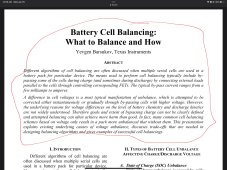
When you balance batteries are you making the under performing cells perform at a higher rate or are you merely resistant training the higher performing battery cell to the lower standards of what is called a balanced state.
Are the weaker cells being required to perform better? That would seem to be the desire. What is the actual price paid to do this and again are we reducing the better performing cells in the process by reducing them? It seems the top performing cells are by-passed in a perfect charging state. Right? Which means you end up with more cycles on a cell vs another. What happens when the charger is removed?

What are the standards for a balance cell condition for a battery?
 

Attachments

  • ED8D350A-EE10-4754-A592-429A4C2C0E8E.jpeg
    ED8D350A-EE10-4754-A592-429A4C2C0E8E.jpeg
    569.8 KB · Views: 15
Not interested in debating the merits of active balancing in this thread. (although i’m sure a decade ago that article may have been interesting)

I fully understand what causes imbalance in my pack, i’m looking for experience on the long term reliability of transformer based balancers - i’ve seen enough to know the long term performance of capacitor based balancers is unacceptable for me.
Inductive balancing should (?) be more reliable, but really in the end it all comes down to the original detailed design, and the quality of the individual components.
Electrolytic capacitors, especially when run at high ripple current and higher temperatures are not renowned for long term reliability.
Its a competitive market, which is unfortunately mostly cost driven.
You get what you pay for (sometimes).
 
Stay away from these.
4 cell bms s-l1600.jpg

They are leap frog switcher based on ETA3000 IC which have a problem with cell voltage sensing due to the multiple IC's running asynchronously causing wiring voltage drop that interferes with the neighbor IC cell voltage sensing.
Hello, can you develop more on this. Im looking to use them in 4S16P 40Ah LFP Pack, studying connecting it Permanently. Would love your input.
 
Hello, can you develop more on this. Im looking to use them in 4S16P 40Ah LFP Pack, studying connecting it Permanently. Would love your input.
Assume you saw the other thread with the schematic.

You can actually get these to work if you only buy the two cell, single IC balancer boards and directly wire each two cell active balancer between two cells in the total series stack and overlap additional two cell boards with their own wires to battery terminals. It creates somewhat of a rats nest of balancing wires with two wires to each cell terminal but each balancer board only spans two cells so they can be placed on top of cells with short wires.

The low cell impedance keeps the two cell balancers async interaction influence to a minimum.
 
To maximize balancing current, it seems necessary to have a boost-buck architecture (for cell-to-cell).

Extract energy from all cells in series (maximizing voltage input) and then buck to a single cell seems like quite a powerful approach, which sidesteps the need for a boost component.

Capacitors seem to degrade over time from drying out and such, which highlights an appeal of inductive type.

However, there has yet to be any "active balancer" (induction or capacitance type) that has proved to be reliable and effective.

I am excited for a future where active cell balancing is considered a well addressed engineering topic :)
 
Back
Top