diy solar

diy solar

What do you think of this Setup? Kisae Abso MPPT/DC-DC based

redmessengerbag

New Member
Joined
Mar 15, 2020
Messages
41
So I've got the Xuba 280ah cells and all of the components for my camper van, I just need to hook it all up! Here is the schematic I came with using Will's guide with Renogy DC-DC/Solar 50a system, but I've replaced the MPPT/DC-DC with a Kisae Abso DMT1250. The reasons why I chose the Kisae is it accepts 24v solar charging, and it is more programmable than the Renogy.

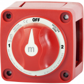
Kisae is only a one way charger go from input (solar/starter batt) to house only, doesn't go the other way. Kisae's tech support has been incredible and has been very responsive with detailed answers to my questions and suggested a battery switch that can combine the two batteries for emergency starting purposes. So

1. normal operation house battery charged by starter/solar
2. house and starter batteries are combined
3. Off, nothing connected (for maintenance

Just wanted to see if this makes sense.

The one burning questions I have is it appears in Will's diagram that the house battery is on a separate circuit all grounded back to the house battery and not to the chasis. However it seems the Abso Charger the 2 inputs and one 1 output are all bonded together with an isolated/separate chasis ground. Kisae told me that both grounds can go to the same chasis ground, but of course with separate wires. Anyhow, I am trying to figure if there are any issues with this. Thanks!

NOTE: The ground in the last part is something i put on the diagram that is not in will's wiring design and I'm not sure if that is appropriate.

1594665048555.png
 
I could totally be missing something, but I'm getting confused because I don't know the wiring diagram of the Blue Sea Switch. Do you have a model # or diagram for it?
 
I could totally be missing something, but I'm getting confused because I don't know the wiring diagram of the Blue Sea Switch. Do you have a model # or diagram for it?

Just standard 3 position blue sea battery switch. The goal is combine two batteries in emergency situations. It's not exactly the intended use of switching between batteries

1594759750636.png
 
The Kisae charger looks interesting I like how you can vary the alternator charge rate in 5 amp increments up to 50 amps to max out your alternator's capacity without harming it.

Does the chassis ground wire on the right side of the case of the Kisae charger need to be the same heavy gauge wire as the main ground wire to handle the same amount of current?

In case of a problem does the on/off switch on the Kisae unit turn everything off and stop all charging or does it just stop alternator charging?

No breaker needed on the incoming solar wires?
 
It would be helpful to add some wire sizes to this diagram. You shouldn't have different size wires landed on the same terminal of a breaker. The breakers should be used to transition wire sizes.

Breakers and fuses protect wiring and not equipment.
 
All wires are 4 AWG, except the thicker ones (if you can tell the difference on the diagram), the thick ones are sized for your specific inverter. I am going with 1/0 Gauge. There are conflicting guides for 2000W inverter on wire size. Kisae recommends a 300a breaker and 2/0 (00) gauge wire. I don't plan going above 1500W and 2000w wasn't much more, so I am sticking with 250a Breaker and 0 Gauge. Some say for short distances 2 gauge is enough for this load. (my load wire will be like 3ft at most to inverter

If you look at Will's diagrams, this is adapted from his. He recommends 4awg. Charging circuit is not going above 50a...load circuit is the one you have to size appropriately.

There's no incoming solar wires yet, I haven't gotten to that portion, I don't remember exactly but I think if below 15amp or something, solar is ok with out fuses, (please verify this yourself), I am not there yet, I will do that in a bit. The on off switch disconnects the charger to the house battery/starter battery. I will use the same 4awg wire for chassis ground, but all going to the negative bus bar, then to chassis ground.
 
It would be helpful to add some wire sizes to this diagram. You shouldn't have different size wires landed on the same terminal of a breaker. The breakers should be used to transition wire sizes.

Breakers and fuses protect wiring and not equipment.

This is how Will's diagram was designed.

For the 250A breaker that has two different size wires you are referring to, the thinner is input for charging the house battery and it's not on the protected side of the 250a breaker, if that makes sense. That same thinner charging on the bottom of the 250a breaker is protected by the 70a breaker coming from the Kisae charger next to it.

On the load side, I do have two different size wires one going to inverter, one going to DC load fuse box. I guess I can probably use the same gauge wires...(just costs me a little more, lol). Alternatively, I can put in another breaker between the 250A and the DC fuse box? Thanks!
 
Under the removable cover where the wires enter the Kisae charger there is a small on/off switch that is almost impossible to reach with your finger. I actually Dremeled the cover to make access easier. Does that disable all charging or just the alternator charging?
I just got a 1250 but yet to install it.

I am not sure honestly. Kisae has incredible tech support though.

The level of detail and thought in their responses are amazing. Feel free to reach out, and please let us know!
 
Kisae tech support paraphrased answers to a couple questions I had:

Question: When connecting the chassis ground terminal that's on the right side of the 1250 charger should I connect it nearby to the metal van wall or better to go to the van battery negative terminal directly?

Whatever is the nearest (typically a good metal chassis point).
And does this wire need to be heavy 4 gauge wire like the battery + and - wires or just a small wire?

First of all, for wires up to 5 or 6 feet long, we suggest using AWG #6 for each one (positive and negative) for a total of 10 feet round trip. If one wire is shorter than the other, you can increase the length of the longest by the same amount of the residual of the shorter to the 5 or 6 feet. For longer wires, you should increase the thickness proportionally to the length to compensate for the increment in the resistance to avoid excessive voltage drop (and so power losses).

For the chassis GND split terminal on the right side of the DMT1250 unit, you can use a wire one-size thinner than the one used for the + and -, provided that the suggested 60A DC fuse in series with the positive is used (as must be).

Question: Sometimes when house battery gets low I need the fastest charge of the 280 ah lithium battery to quickly top-off for the night so what settings would be best to get the charger in "bulk" charge mode the fastest and longest without worry about float etc?

Select the max. charging current in the “h” setting parameter as per the battery manufacturer. Please take into account that that value is per battery basis. If you have “n” batteries (same type) connected in parallel, the total max. charging current is the sum of the per battery ones, i.e. Total-Imax = n x Imax-per-battery.

Then, select the medium or even the lowest termination current, corresponding to the “L” (Low) setting parameter, to pass from Absorption to Floating, as long as the battery does not get excessive warm (hot). Otherwise, return to the next higher value of the parameter “L” (Low).

The lower the “L” (Low) setting is, the longer the unit remains in the Absorption stage before passing to the Floating one, and vice versa.

The longer the Absorption stage the higher the state of charge “SoC” of the battery.

Of course, the above statements are possible as long as the charging sources are available all or most of the time in all the charging stages (both the CH3 starter battery and the CH2 solar panel input port charging sources are variable by nature [e.g. engine r.p.m. speed, sunlight conditions, etc.]).
 
I'm currently considering going with the Kisae DMT1250 over the Renogy DCDC50S, however the Renogy's ability to trickle charge the starting battery from the PV input is the main thing that's keeping me from just pulling the trigger on the Kisae.


Just standard 3 position blue sea battery switch. The goal is combine two batteries in emergency situations. It's not exactly the intended use of switching between batteries

Just for clarification,
So by connecting the house battery and starting battery via this switch, you are able to access their combined voltage to start the vehicle?

But, this does not actually *charge* the starter battery?

Also, what would happen if you left them connected via the switch after the vehicle starts and the alternator kicks in?
 
I'm currently considering going with the Kisae DMT1250 over the Renogy DCDC50S, however the Renogy's ability to trickle charge the starting battery from the PV input is the main thing that's keeping me from just pulling the trigger on the Kisae.


Just for clarification,
So by connecting the house battery and starting battery via this switch, you are able to access their combined voltage to start the vehicle?

But, this does not actually *charge* the starter battery?

Also, what would happen if you left them connected via the switch after the vehicle starts and the alternator kicks in?

You are basically taking the charger out of the circuit and connecting to two batteries in parallel...with nothing controlling charge from house to starting. It certainly "charges" but not the kind you want for any extended periods
 
So then do you need to disconnect the solar and turn off the charger, or does the Kisae automatically shut off? It's my understanding that if you have a charge controller connected to PV input but no battery bank/output that it will fry the controller.
 
I talked to tech at Kisae and he said that the unit doesn't have a problem on disconnect.

I specifically called about that because I heard someone fried his Renogy DC-DC unit when the BMS in his battery cut off for something like low temp safety and it caused the damage from backfeeding. From my understanding after talking to a tech at Renogy it was sent back and they were trying to duplicate the problem and if found fix it some how and that was all back around January.
I was supposed to call back to find out if they fixed it but since found out my alternator can't handle a steady 50 amp draw anyway so never did buy one.
 
I have the Overkill BMS but still putting the system together.
The trouble Renogy potentially may have had was not BMS specific but that when any BMS stopped flow to the battery the DC50 charger was damaged. Again this was way back around January and may have been an isolated problem from one person reporting it so the tech at Renogy cautioned me to not buy one until they examined the possibly defective unit and were sure that they had had fixed it if it was even found to be a widespread problem or just an isolated incident..
I don't want to bad mouth Renogy there may not have been an actual problem just reporting what they said back in January.
 
I don't have anything that draws over 500 watts (water heating element) and mostly use propane for heat and cooking.
 
Anyone figure out the actual voltage limit for the Kisae DMT1250?

I'm finding varying information from multiple sources. Some say 32v, 45v, or 50v.
 
Last edited:
Back
Top