diy solar

diy solar

Where is @Will Prowse?

Exactly. Resistance builds up heat which is expelled through connections and through wire. Does the heat just magically appear?

With it being a 25 year old truck, I imagine that older wires and higher resistances adds to the current draw. What might be 25a at the glow plug, could be 30a at the battery right?

Bad connections can make the current go down due to higher resistance, but the current will always be the same at all points in the circuit.

.. but bad connections and such certainly can increase resistance which would increase current...
In order for the current to increase due to a bad connection the Voltage at the source would have to increase..

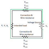
1666824473824.png

  • The current in the circuit will always be the same at all points in the circuit.
  • The current in the circuit can be calculated as the Voltage of the power source divided by the sum of all resistance in the circuit.
  • The voltage drop across the various resistance points in a circuit will always add up to the voltage of the power supply
  • The power being provided by the Power Supply will be the same as the sum of the power dissipated at each resistance point

  • If the resistance in a connection goes up, the current in the circuit will go down because the total resistance of the circuit went up (I = V/R),
  • If the resistance in a connection goes up, the voltage drop at the connection will go up and the power dissipated at the connection will go up. Note that when the voltage at the connection goes up, the voltage at the load must go down. (This is assuming everything else, likw Vs, stays the same)

The above statements are for DC. AC is more complicated but at a first approximation, it is the same.
 
Bad connections can make the current go down due to higher resistance, but the current will always be the same at all points in the circuit.


In order for the current to increase due to a bad connection the Voltage at the source would have to increase..

View attachment 117967

  • The current in the circuit will always be the same at all points in the circuit.
  • The current in the circuit can be calculated as the Voltage of the power source divided by the sum of all resistance in the circuit.
  • The voltage drop across the various resistance points in a circuit will always add up to the voltage of the power supply
  • The power being provided by the Power Supply will be the same as the sum of the power dissipated at each resistance point

  • If the resistance in a connection goes up, the current in the circuit will go down because the total resistance of the circuit went up (I = V/R),
  • If the resistance in a connection goes up, the voltage drop at the connection will go up and the power dissipated at the connection will go up. Note that when the voltage at the connection goes up, the voltage at the load must go down. (This is assuming everything else, likw Vs, stays the same)

The above statements are for DC. AC is more complicated but at a first approximation, it is the same.
Learn something new every day!
 
... but bad connections and such certainly can increase resistance which would increase current...
No, increased resistance equals decreased current at a fixed voltage (Like from a fixed12v source).
E=IR for DC circuits.

Ohms LAW.
Bad connections can make the current go down due to higher resistance, but the current will always be the same at all points in the circuit.

In order for the current to increase due to a bad connection the Voltage at the source would have to increase..

It is SMPS, like our inverters, where input resistance increases the current draw.
They are designed to deliver constant output voltage (into whatever load), so if low battery or resistive connections reduces voltage in, they suck more current to get same power.


I thought the glow plug circuit in older diesels latched on due to current, and as glow plugs heated up and increased in resistance, current decreased, until it switched off. Mine is a 1995, think that's how it works but haven't dug into it (ain't broke yet.)

Your newer ones probably have software somewhere.

My ancient farm Cats don't have glow plugs. But Ether can be sprayed 4' and is sucked into the intake.
(or at least they worked that way 25 years ago last time I operated them.)
 
It is interesting how the subject of this thread has wandered around....:)
Many post comments deserve a little side discussion from the post, especially when basic electrical concepts are being introduced to the person posting in error so their comments are more grounded on facts in the future.
 
It is SMPS, like our inverters, where input resistance increases the current draw.
........................
............
I believe that you are refering to output load resistance at the inverter output. (that's an ac circuit).
I think of current as always being pushed, not drawn, in a resistance only circuit (no inductance or capacitiace).
Charged particles (most commomly electrons (-)), are pushed thru a circuits resistance by voltage, not drawn thru the circuit by resistance. Take the voltage away and the current goes to zero. Increase the resistance and the current is reduced.
E=IR once again.
 
Last edited:
I'm referring to resistance of long wires, or of a poor connection.
If the inverter was trying to draw 100A from 12V battery and poor connection added 0.010 ohms, that drops 1.0V so inverter sees only 11V.
To get the same 1200W it now has to draw 109A. So input resistance causes increased current draw.

Battery voltage pushes musical chairs (1) into a wire, against resistance or in the case of SMPS inductance. SMPS connects/disconnects inductor (and lets current fly back through a diode or FET) to regulate that current. So the battery may push, but the switcher controls the current.

1) Professors tell us that it is holes moving, not electrons. You're dancing to the music, and when the music stops you have to take a chair. Did the dancers move, or did the (empty) musical chair move? I believe in electrons, but at least in doped silicon, motion of electrons vs. motion of holes can be distinguished with the Hall effect. Some silicon is P-type, some is N-type


Maybe that's why I like working with vacuum tubes. Unlike Paschen discharge where ions are moving, in a vacuum all you have are electrons (except for whatever gets sputtered off the electrodes.)
 
I'm referring to resistance of long wires, or of a poor connection.
If the inverter was trying to draw 100A from 12V battery and poor connection added 0.010 ohms, that drops 1.0V so inverter sees only 11V.
To get the same 1200W it now has to draw 109A. So input resistance causes increased current draw.
I see what you are saying and yes, with the inverter the current will increase..... but it is because the inverter is not a fixed 'resistance' and this results in multiple variables changing. When the resistance at a connection goes up, the inverter will effectively lower its input 'resistance' till the current increases to a level that compensates for the increased power loss across the connection.

(I put resistance in quotes because the inverter circuit is far more complicated than pure resistance. However, it still works to think about it as resistance.)
 
Sssoooo, back towards the original topic. I would like to say that a sticky for video ideas would be nice but with the tendency of threads getting derailed that probably wouldn't work.

In light of that, video idea (or maybe a sticky?):

Things Everyone Just Knows (But Nobody Tells You):

Rules of thumb like
Inverters and panel output should be calculated at 85% efficiency
fuses and breakers are Amps * 1.25%,
sunlight hours are NOT daylight hours,
shoot for 3 days capacity on your batteries and so on
weather and location make all the difference

DC charging amps are NOT the same as AC charging amps from your generator

I love the beginner videos you put out @Will Prowse because there is a wide range of skill and experience levels and as more and more people get into solar it's nice to see videos to help the new folks get at least the basics without having to dig and search for information that they don't know they don't know. I was playing with solar stuff in Western WA where solar is pretty much a joke for years before I ever found your videos (I think I was on my 2nd or 3rd attempt about the time you got your house) and at the time information wasn't really out there to learn from and trial-and-error WERE the only way to learn. The paywall to get started at the time was also very hard to deal with as the equipment available started at MidNite Solar and Victron and went up from there for the most part and if you could get panels for less than $2/w that was a helluva deal. Nowadays things are so much cheaper and a bit easier to get past that paywall and still have a usable and reliable system.

Now that technology has changed quite a bit since your original videos came out it's nice to see some beginner friendly videos again. Keep putting those out there please! ?
 
My idea for new videos is a solar version of those home makeover shows. Find janky systems and show the owner/installer what they did wrong and how to do it right.

It would be great content!
 

diy solar

diy solar
Back
Top