diy solar

diy solar

Why not to use Daly BMS with MPPT controllers

What's critical for overvoltage protection is that your crowbar device(s) are able to blow the fuse/trip the breaker before failing themselves. Many fuses have datasheets that show how many amps and time to blow.

The datasheet for the overvoltage protection device in question will have a plot of how much volts and current and time or total energy they can handle.
I just tried to find a 250V, 100A fuse on Digikey. Alas, the biggest is 60A is their largest fast blow, 250V fuse and they have no data.

Most of the fuse data I've seen for lower current fuses makes me think that double the rated current is going to take like a few seconds to blow. The design problem is that the PV array, directly through a failed MPPT or PWM buck converter can't provide that much current into a short curcuit. A bit less than the rated SC panel current. The MPPT/PWM regulator was boosting current while reducing voltage.

So my solution of a standard crowbar overvoltage is not going to blow the fuse for the situation of HV array, MPPT fail, unless the MPPT controller is set to limit current about half the PV short circuit current, and the fuse is just over that. But, if the SCR type crowbar is rated well above the total short circuit PV current (the SC current of each series string added to each parallel string), then it will keep the PV panels shorted out indefinately, something that the earliest PV charge controllers did. I don't like this as well as blowing a fuse, so I'll keep thinking and hope to come up with a better solution.
BruceM
 
I'm a retired EE/CS with my own custom 120VDC, off grid power system; I'm new here, and I'm considering LiFePo4 and a new custom 39 cell BMS/balancer for my 120VDC battery bank.

I think this is a most valuable failure report and and failure analysis video posted by BlueFlower. Bravo. I appreciate it and have learned from it!

The switching MOSFET in any PWM or MPPT will typically fail as a dead short. Most are a buck converter design topology (step down only) since that is the simplest and highest efficiency. When the switching MOSFET in a buck converter fails, it causes full on, full PV voltage sent to the BMS. I'd bet few commercial BMS systems are designed to cope with this typical failure of the PV charge regulator. They should, and it's important, which is why Blueflower's report is important. He's illustrating a serious flaw in the illusion of BMS protection. If a BMS with high voltage protection isn't available, then you'd have to add a voltage limit protection on the PV regulator output; and this is not a standard product. The external voltage limiter must disconnect or short the PV regulator output before voltage rises above the capability of the BMS, fast enough to protect the BMS. Overvoltage will typically fail-short the MOSFETs in the BMS disconnect switch, so now you have directly connected your PV arrays to your batteries.

Something to consider seriously for systems with typical high voltage PV down regulated by a bucking (topology) PV regulator. A PV regulator fail can destroy the BMS and all of your batteries. Software assigned voltage limits on the PV regulator offer no protection at all for this failure. A horrible, costly failure. I'd sure not want to be using a cheap, bucking PV regulator over half it's rated capacity. You shouldn't risk a major (to you) battery investment without addressing this PV regulator failure mode.

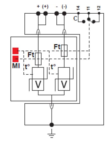
My first thought for a solution is a fuse and overvoltage detecting zener diode SCR crowbar circuit after the PV regulator to protect a BMS. The SCR would clamp down the overvoltage while waiting for the fuse to blow. The crowbar has no affect on the circuit in normal operation and won't fail as a full on as a solid state (MOSFET) switch/relay will. This is not a very difficult circuit, and if someone has an urgent need for it, I'll try to work it up. There may be some industrial DC voltage limiters/crowbar protection circuits available

Thanks again to BlueFlower.
BruceM
Bruce PMed you about this circuit as I am interested.
 
An example of a high amp SCR module:

This is an SCR module rated for 800V and 300A. $53. So just shorting out the PV in case of overvoltage, without a fuse is a viable approach. Once it's triggered (via zener diode circuit), you'd have to flip the PV breakers/disconnect to turn it off.
$53 is nothing compared to what many of us are spending on these batteries so this will work to protect a BMS in case of scc failure?

 
I am thinking about how to protect my system
  1. DC breaker and/or DC fuse. Here the V goes high (24V->90V) while the current is low like 1-10A
    Even if I use a crowbar circuit if 90V and 1A is produced by the solar then the fuse will not blow.
  2. DC over voltage protector? Is there one that can handle 48V and 100-200A ? And it usually uses a relay (again a possible SPoF).
  3. BMS with relay ... seen problems with that like @Off-Grid-Garage Andy had.
Victron has one 48V battery protector, but it is only for the charge side. Can not used with all-in-one inverter/chargers.

This over voltage protector seems to work two ways:
1, shorts and/or grounds the over voltage
2, can switch a relay

https://citel.de/en/ac-power/type-2-dc-surge-protector/ds230s-48dc

MFG_DS230S-48DC.jpg
DS230S_plug.jpg


But a bit expensive about $130.

Any other ideas?
 
Last edited:
It is good to check how fast the circuit needs to be. In the worst case, the MPPT fails when there is no current flowing and the input capacitors of the MPPT are charged to the ~80-90VDC. Suddenly the MPPT completely fails and connects the input to the output.
The BMS contains MOSFETS which will almost instantly go into avalanche mode because the voltage is far above the maximum.
I think the crowbar should react very fast or at least keep the voltage down enough until the fuse blows. A TVS diode could be a good choice, but the design needs to ensure that the TVS and the PCB can handle the capacitor discharge current.
The question is: will the fuse blow? Depending on what the short circuit current of the PV is, it is will or will not. Any ideas, BruceM?

A second approach is a BMS where the FETs are rated with higher voltages, higher than the OCV of the PV installation. However the higher the FET voltage rating, the more resistance it has so you need more FETs. It is possible that the Daly 200A version is fully crowded with 40V FETs and that more 100V FETs will not fit on that PCB + make it much more expensive.

A non-FET based BMS + mechanical relay makes the design more reliable.
 
So, my last 3kw inverter blew up when I put my 1/4 hp garage door opener on it and I bought it off Amazon with the asurion insurance so I had $350 plus a $50 Amazon gift card to put towards a new inverter and got this All In One unit with only $200 out of pocket and it has asurion insurance agin just in case :) unfortunately my LiFePo4 batteries that are coming hopefully within a month or two don’t have insurance so…I’ll be putting 4 Sunpower T5 solar panels 2S2P? To get about 120vdc and 10 amps going into the on board 80 amp 140vdc mppt charger. I will put the appropriate fuses between panels and charger and charger and batteries and a 16s 100a Daly dumb BMS connected to my lishen 150ah LiFePo4’s. I would hate for the Mppt in this system to send 120vdc into my battery bank. What should I put between the mppt and batteries?
 
Last edited:
Or maybe this? I’m not sure how closely I need to match PV volts and amps to the thyristor.

I’m just not sure what the voltage and amps rating of this module means for my application.
 
Last edited:
whatever you listed in your first post does not show...it says invlaid request...you might want to repost using a different link.
Okay I put it as a link in the word “this” it’s just an 800v 240A module, like I said in my last post I’m just wondering what the volts and amps mean.
 
Not common in the sort of BMS we all use but to meet IEC 62133-2 a BMS must be single fault tolerant. This is often done with a secondary chemical fuse. They are electronically triggered if the primary FET's have not cleared the fault.


I have secondary protection by using a DC rated MCCB with a shunt trip. 36 kA breaking capacity at 750 VDC. If that doesn't trip something spectacular has occurred!
Not sure if the Daly is single fault tolerant, as the mosfets can fail if an overvoltage is applied. If mosfets fail, they can keep conducting. This is not going to trigger any fuse, I expect as the current is normal.

About the schematic: a TVS + small shunt resistor + opamp measuring voltage over shunt could do the trick. As soon as the TVS starts conducting, a current is detected by the opamp through the shunt resistor. The opamp then could trigger a relay to turn off for example.
 
My BMS opens a contactor between the SCC and the PV array combiner box in the event of an overvoltage situation.
 
Not sure if the Daly is single fault tolerant, as the mosfets can fail if an overvoltage is applied. If mosfets fail, they can keep conducting. This is not going to trigger any fuse, I expect as the current is normal.

About the schematic: a TVS + small shunt resistor + opamp measuring voltage over shunt could do the trick. As soon as the TVS starts conducting, a current is detected by the opamp through the shunt resistor. The opamp then could trigger a relay to turn off for example.
Would these work?
TVS - $22.335
Small Shunt Resistor - $16.8
OPAMP - $5.25
Oh and I guess I need a Relay - $50
 
so in the questions, the youtuber said that he had an "esmart" mppt SC controller. Did a quick google and came up with some standard looking fan cooled chineese SCC.
Interested finding what model and what failed in the Esmart mppt.... I'm using a Esmart3-60, 150v input though only feeding it 48voc. Willing to risk worthless 13 year old flooded but not LiFePo. Has anyone ever send 100v through a 12v lead acid battery?
 

So there is a major problem with these type of BMS.

Any thoughts?
Daly does not allow you to series connect their BMS. That tells you the FETs are not rated for 48v except in their 48v models.
FETs have a propensity to fail as a short, and not just in a BMS. Your inverter has them, most likely your MPPT controller does as well.
So, basically don't use a solar charge controller, a BMS, or an inverter with your batteries.

Now, JBD rates their to withstand 80v. Part selection is key, as is quality control. Daly does not have a good record for quality control. Apparently neither does the manufacturer of his MPPT.

Most electronics will die if exposed to almost 3 times their rated operating voltage for a great length of time. (24v to 90v)
To blow the vents on those cells, they were either nearly full, or exposed to this over an extended period of time.

Faulty MPPT, blame the BMS?
 
He mentions an Electrodacus, but would it protect against that too? Sure... because you're forced to use low voltage on the most primitive solar charge technology around. No more MPPT and you're roped into 60-72 cell panels in parallel only.

Electrodacus uses FETs to turn on and off charge current as well. You can of course use a relay instead of the DSSR units (and hook up an MPPT).
 
Back
Top