diy solar

diy solar

Why not to use Daly BMS with MPPT controllers

Electrodacus uses FETs to turn on and off charge current as well. You can of course use a relay instead of the DSSR units (and hook up an MPPT).
Or a Victron MPPT that can be directly controlled by the Electrodacus.

No need to use Dacian's PWM controllers.
 
This charge controller I use has a signal "Help! Disconnect! I've Failed!"

"If a switch in the charge controller short circuits, the battery may be irreparably damaged. If a short circuit occurs in the charge controller, the battery is no longer protected against overcharging.
• MSTE SOLAR GmbH recommends using the signaling contact to ensure that, in case of a failure, the battery is disconnected from the charge controller by a relay or contactor."


I concur,

Just shorting out the solarpanel is a viable option.


I did think about using an SCR to crowbar the PV array.
But inside an MPPT, I think there is just an inductor and a MOSFET between battery and PV. There will be a flyback diode, but no blocking diode. If MOSFET shorts, then crowbarring the PV array is shorting battery to ground through the charge controller. That's where the fast blow fuse comes in. SCR needs to handle about 5x fuse rating, about 6x normal charge current, could be 12x normal PV current depending on how much step-down in voltage.

If you have a polarized breaker between battery and SCC, hope you got the orientation correct.

This is the safest way to do it.

<open contact between PV array and SCC>

Need to find a pretty high voltage relay, typically 150V to 600V depending on SCC.
 
Or a Victron MPPT that can be directly controlled by the Electrodacus.

No need to use Dacian's PWM controllers.
They aren't a PWM controller, they are just an on/off FET, which was my point. The Victrons use FETs as well, which was also my point.
 
Hi all
The video posted as the subject of this discussion was posted on YouTube by myself. Ask any additional questions. It is good to see some here have come up with similar possible solutions as I was thinking such as voltage triggered SCR or something like that. I will be investigating these a bit more. Some were asking the string voltage. It was fed with 120v. Esmart 3 cc rated to 150v. High side FET shorted, smallish 100w panels meant then current limited down to 4 amps or so and just kept going. Out of interest I capacity tested of these abused cells last night and it was 230ah out of 280ah. As seen in the video two sets of the four FETs were shorted in the BMS obviously due to overvoltage. This system now has new cells and a diybms with mechanical relays looking after things.
Jason
 
MOSFET's are a significant cost of the bms. MOSFET cost is greater the greater the current rating (lower Rds_ON) and the greater the voltage breakdown rating. Typically bms's only put breakdown rated MOSFET's based on voltage rating for BMS. In this case it is a 24v bms. It appears his BMS's MOSFET's are 40v breakdown which should be fine for a 24v system.

A higher breakdown voltage MOSFET will also have a greater Rds_ON resistance for same size/cost so a higher breakdown voltage MOSFET is going to require BMS to have more in parallel to get the required series resistance for the series pass switch BMS current capability. This adds cost and PCB area.

The root problem is his PV charge controller shorting out allowing its battery charging output to go to 90v. Also wonder what happened to his 24v inverter when subjected to 90v?

Expecting a BMS or inverter to take a voltage over twice its maximum limit is not reasonable. What would the guy expect of bms if his MPPT controller was running with 150v of series panels?

PS, I have seen some cheap 24v BMS's built with 20v breakdown MOSFET's, counting on spec margin of MOSFET's to survive. Also beware of using low cost 12v LFP batteries with internal BMS for a series stacked battery array for 24v or 48v systems. Many times their internal BMS is built with 20v MOSFET's which are fine if only operating a 12v system. You might get away with it for a 24v system, but again, you are relying on MOSFET breakdown voltage margin to spec.
 
A simple overvoltage protection would be fuse - MOV - fuse !
1st from the MPPT charger into the MOV, specced just slightly above max normal charging voltage (Also please note max charging voltage cut off should not exceed 3.55V/cell X Number of cells, for increased life-expectancy of cells) That enables the MOV to be specced at 3.75V/cell X number of cells.
2nd fuse towards the battery bank, such that in the event the MOV gets triggered and thereby shorts accroos + and - then it also blows the fuse from the batteries.

Br
Watch Out
 
A simple overvoltage protection would be fuse - MOV - fuse !
............. specced just slightly above max normal charging voltage (Also please note max charging voltage cut off should not exceed 3.55V/cell X Number of cells, for increased life-expectancy of cells) That enables the MOV to be specced at 3.75V/cell X number of cells.
2nd fuse towards the battery bank, such that in the event the MOV gets triggered and thereby shorts accroos + and - then it also blows the fuse from the batteries.

Br
Watch Out

A fuse is designed for over-current, not over-voltage.
 
MOV clamp blowing fuse might be the first idea that comes to mind, but it doesn't have a suitably sharp IV curve.
Look through the data sheet to graphs "LEAKAGE CURRENT & CLAMPING VOLTAGE CURVES"
What you need is current so low that it won't drain the battery, transitioning sharply to current which blows fuse. It doesn't have such a response.
Also, these devices are meant to clamp a fast spike of milliseconds or microseconds. They absorb the energy, turning it into heat. During relatively gradual charging they would simply burn up.


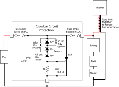
What you would need is a reference voltage. Could be MOV or Zener with resistor, or something else. Whatever has the accuracy and stability desired. Feed that and battery voltage into a comparator. Use that to drive a FET, SCR, or other switch which then crowbars the battery, blowing fuse.

I have a charge controller with such an "overvoltage" signal. Maybe I can rig up a solenoid to trip the PV breakers. I suppose with ganged breakers, I could overload one to trip the others, rather than making a mechanical kludge.
 
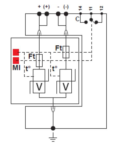
MOV's are not good for this application due to their soft zener and poor voltage tolerance. There are crowbar modules available. I believe there are some SCC's that have the crowbar in them.

A nearby lightning hit can short out a charge controller. Charge controller should at least have MOV's across their PV inputs.


Crowbar circuit.png
 
Last edited:
MOV's are not good for this application due to their soft zener and poor voltage tolerance. There are crowbar modules available. I believe there are some SCC's that have the crowbar in them.


View attachment 60772

Do you know any product that we can use ?

I just found this MOV based and relay control extended item. And it is not cheap

MFG_DS230S-48DC.jpg
DS230S_plug.jpg
 
Do you know any product that we can use ?

I just found this MOV based and relay control extended item. And it is not cheap

MFG_DS230S-48DC.jpg
DS230S_plug.jpg

That device is a surge protector. Again not a sharp enough knee to be a crowbar for battery over-charge.

Purpose is to absorb transients from nearby lightning strikes or inductive kick from loads. Usually these allow moderately higher voltage, like 900V on a 600V circuit, clamp above that. Electronic devices are supposed to handle brief over voltages, and surge protector limits it to something that won't cause damage. But the circuit can't take a sustained voltage so high, and neither can these surge protectors. They dissipate power = clamping voltage x current; small enough amount of energy for a millisecond. The only way to deal with sustained over-voltage is either open circuit or clamp to zero volts.

Here are more surge protectors, for AC and PV circuits:


That device is a surge protector. Again not a sharp enough knee to be a crowbar for battery over-charge.
I am not afraid of battery overcharge. The BMS will handle that. Also not searching for anything related lightning.
But if there is a malfunction in a MPPT (like the example) where 100-200V 15A is put on the 24-48V line ... a fuse will not blow (15A only) ... BMS can burn out .... so I can not find a product to protect battery from this scenario.

BMS disconnects when battery voltage gets too high. With no load, voltage on BMS rises uncontrollably. That is where a crowbar circuit would work. In this case you don't need such a sharp knee in the sense circuit. If on battery side of SCC, needs to be low enough leakage at proper voltage to avoid draining battery.

You could design a circuit to detect something like 20V for 12V battery, and trip a crowbar. The crowbar needs to latch closed, so it doesn't toggle on and off like a typical relay would. There are latching relays, and there are SCR. You could also consider using a 2-pole breaker as a crowbar relay.

As I mentioned, I thought about mechanically tripping the PV breaker to open it. Then I thought of putting over-current through one more pole of a ganged breaker. Assume you had three PV strings combined in parallel. Use a 4-pole breaker and route a suitably high current source to the 4th pole, shorting it out in order to trip the breaker.

A few issues making this work. If you route the combined PV wire to that breaker, it would only trip same rating breaker under full sun conditions, and only after a delay. Would need a lower amperage rating to trip fast in full sun. Under partial sun could still be slow. If feeding circuit from battery, BMS has already disconnected. Need to bypass BMS or use other battery to supply trip current (in my case, AGM so not disconnected.) Breaker needs to withstand short-circuit current available, so maybe use a series resistor.

SCR circuit seems the cleanest electrically. Needs to be heatsinked to carry Isc while in the conducting state (perhaps a volt or so across SCR.)

When you build it, show us :) I am curious.
I was thinking only simple things like V meter (with RasPi) and then release relay with it.
 
Back
Top