diy solar

diy solar

Will a battery bank 'pull down' the voltage of an AC-DC charger (for instance a laptop power brick) in the same way a PV panels voltage is pulled down

The question of powering a solar charge controller with something other than a solar panel came up within the past few months and the reaction at first was that it was not going to work. Based on the few threads I've seen, it does work. It may not be ideal, but the solar charge controllers seem to tolerate it.
If I'm thinking of the same discussion (and I may not be this question comes up from time to time) it may have related to PWM controllers

As usual, the clever Chinese engineers have you covered. Search on eBay, or AliExpress, for “Lithium Battery Charge Controller”. There are dozens/hundreds offered there for sale. They are brilliant, and very low cost, but limited to about 10 amps output.
Interesting, never heard of these before. So what are they exactly? DC-DC converters with a 3 stage charging algorithm?
You connect your own “dumb” power supply as the input,
This sounds like exactly the sort of thing I'm looking for.

For higher amperage charging, I would try using my solar charge controller, as mentioned above.
Do you have any thoughts on what @MattiFin mentioned last night:
Very small mptt controller might work if the laptop power supply has enough power to ”overload” the mptt controller.
large mptt controller would attempt to track for maximum power and shut down the laptop power supply.

No, the DC-DC converter does not need to be limited in capacity. A converter rated at 20 amps maximum would be fine. That is just the maximum amperage cab be drawn from the device without damage. It is a bit like driving a muscle car with a big engine. You have that potential power under the hood, but you don’t need to use it.
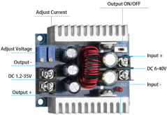
Thank you for the explanation, what I was referring to was not the actual rating of the DC-DC but the current adjustment. The DC-DC I am looking at looks like this:
Screenshot_2021-01-25 s-l1600 jpg (JPEG Image, 1200 × 1200 pixels) — Scaled (76%).png

What I am trying to understand is whether the current adjustment screw must be set to some value below the max current of the laptop power supply. Say the DC-DC is rated 20A, output voltage set to 13.8V for a 4s battery, the laptop power supply is 12A, 19.5V, would the DC-DC need to be set to <12A to keep the laptop power supply out of hiccup mode / ocp.
 
A constant current constant voltage power supply lowers its voltage to control the current flow to the battery.
Said another way its the difference in voltage between the power supply and the battery that determines the flow.
Garden variety power supplies don't have this feature.
I'm starting to understand better the piece I was missing (which was the point of this thread). Thank you.
So the CC/CV power supply will essentially be continuously modifying voltage to stay below its current limit. Whereas a CV(?) supply can only be used in contexts where the difference in voltage is small enough where (V/R = I) that current doesn't exceed the rating of the charger. Am I on the right track more or less, or still confused?
 
Laptop power supply and solar charge controller probably wont play nicely together.
Solar panel is essentially current limited source. Pwm-based controller would be really nasty with laptop power supply(constant voltage without active current limiting.

MattFin,
I don’t understand what you mean. In what way is a solar panel more of a “current limited source” than any DC power supply? Why do you think a PWM charge controller, which is not much more than a buck/boost converter, not work well with a voltage regulated input? Maybe I’m not seeing something.
 
So the CC/CV power supply will essentially be continuously modifying voltage to stay below its current limit.
At its limit but yes.
Theorectically cc/cv power supply you should be able to short the leads and get its rated amperage.
Whereas a CV(?) supply can only be used in contexts where the difference in voltage is small enough where (V/R = I) that current doesn't exceed the rating of the charger.
I think this is correct but have not heard them referred to as CV.
 
  • Like
Reactions: Dzl
What would be a better term? I have only heard "dumb power supply" which i suspect isn't the technical term ?

Dumb power supply is a very good term. You are trying to think a power supply, into a charger. Thinking all day and all night won't make it happen. They are not the same devices... at all. A power supply is PART of a battery charger. The rest of the control (as in bulk, absorption, float as example) is the other part of the battery charger

Plug your power supply laptop or other wise, into a SCC. Which is nothing more than a battery charger WITHOUT a power supply. (normally powered by a solar panel.) Its like peanut butter and chocolate. Too great tastes that taste great together

So in short hand

Power supply + charge controller = Battery charger

There is no other way
 
Long ago, portable devices came with a wall-wart, and there was as warning not to connect a different supply.
I thought, "Yeah Right!"

Turns out this was a trade-off to make an economy device. The charging circuit in the device didn't regulate down the voltage, rather just had a tiny transistor without much heatsinking or ability to dissipate heat. The impedance-limited wall wart allowed its output to be pulled down to battery voltage, and the device could disconnect when desired charge voltage was reached.

Connecting a stiffer supply would force battery voltage higher and drive in too much current.

What you can do is add series resistance. I have sometimes connected a headlight bulb in series between a dead battery and a battery charger. Sometimes I haven't, ignored the repeated clicks (overload disconnect), and killed the charger.

I've also heard of current limiting circuits made with a transistor and base appropriately biased/pulled by voltage on sense resistor. Maybe too much work, maybe OK with a depletion-mode FET.

So I suggest KISS. Add a resistor to a dumb power supply. (So long as you have that high-voltage disconnect you mentioned.)
 
If I'm thinking of the same discussion (and I may not be this question comes up from time to time) it may have related to PWM controllers


Interesting, never heard of these before. So what are they exactly? DC-DC converters with a 3 stage charging algorithm?

This sounds like exactly the sort of thing I'm looking for.


Do you have any thoughts on what @MattiFin mentioned last night:


Thank you for the explanation, what I was referring to was not the actual rating of the DC-DC but the current adjustment. The DC-DC I am looking at looks like this:
View attachment 34582

What I am trying to understand is whether the current adjustment screw must be set to some value below the max current of the laptop power supply. Say the DC-DC is rated 20A, output voltage set to 13.8V for a 4s battery, the laptop power supply is 12A, 19.5V, would the DC-DC need to be set to <12A to keep the laptop power supply out of hiccup mode / ocp.
Since it is showing a current setting, it certainly looks promising for $10. Certainly most power supplies would work fine if you limit the current/power to 75 to 80% of the power supply rating. Like a previous analogy to cars, you need a throttle setting between full and off. Usually the laptop has the circuit to throttle.
 
Dumb power supply is a very good term. You are trying to think a power supply, into a charger. Thinking all day and all night won't make it happen. They are not the same devices... at all. A power supply is PART of a battery charger. The rest of the control (as in bulk, absorption, float as example) is the other part of the battery charger
I hear what you are saying, and generally speaking, "just buy a charger meant for the job" is good advice, especially considering the subforum this was originally posted in (side note: its been moved into the dangerzone section)

I understand the difference between a 3 stage charger and a simple power supply (to a degree) but I'm using this discussion to expose my (and maybe your) areas of misunderstanding, as well as to solidify the things I think I do understand. So far its been very productive for me at least. I think we agree roughly on the difference between a power supply and a charger, the way I think of it, a charger is more sophisticated it can apply some sort of charge logic (whether that be stages or charger termination, etc). IDK if this is a technically correct understanding but it illustrates the difference between a DC-DC charger and a DC-DC converter pretty well for instance.

But where we differ, is that I think you can effectively use a power supply to charge a battery provided that you understand what you are doing, and have a means of charge termination. There are certainly tradeoffs (without stage 2 there is less time for the BMS to balance and the battery won't be fully topped off to 100%)

Plug your power supply laptop or other wise, into a SCC. Which is nothing more than a battery charger WITHOUT a power supply. (normally powered by a solar panel.)
This is a good way to think of it.
So in short hand
Power supply + charge controller = Battery charger
There is no other way
I think there is another way though, a proper charger with a LFP profile is the simplest solution, but not the only solution.

LiFePO4 doesn't need stage two (CV) or stage 3 (float) of 3 stage charging (though their are good reasons for stage two, and convenience in stage three)

The SBMS0 (which is admittedly a very unique design model) is an example of a design model that is designed around using simple (current limited) charge sources (i.e. PV panels (with no traditional charge controller) and meanwell type CC/CV power supplies). But the important point to understand is that the BMS takes on some of the responsibilities usually performed by the 'charge controllers'. The most important of which is charger termination, and re-connection.
 
Usually the laptop has the circuit to throttle.
This is another topic I've been wanting to explore.
How charging is handled with a laptop or cellphone. What controls the charge, I assume it must be integrated into the laptop, but beyond this I'm unclear.
 
If I understand CC / CV (and I'm not sure that I do beyond a basic practical level), constant current limits the output to a certain maximum current, CV sets the voltage to a certain target. When the difference in voltage is high, the 'load' maxes out the CC rating and the charger operates in CC mode, as the battery is charged its voltage rises and at some point the difference in voltage will be small enough that current (I = V/R) will drop below the max CC at which point the charger is operating in CV mode current tapers and voltage flattens at its set point. Is this roughly correct in your understanding? Or am I fundamentally misunderstanding things?

That is a fairly good explanation. But don’t think of it as the voltage difference that maxes out the charger. It is better to think of it as the battery internal impedance being low because of a low state of charge. What happens in the battery is that, as it is charged, internal battery impedance rises, which means more resistance to current flow.

Going back to the solar panel example, an ~18V solar panel hooked up to a ~12V battery works without a DC-DC converter (MPPT) to convert the voltage and even without a PWM controller if you are not concerned with 3-stage charging so long as there is a means to disconnect the PV array from the battery before the voltage of the battery gets too high. Does this sound right to you?
Yes, but maximum battery life requires that you adhere to the manufacturers recommended charging voltage. The battery will accept a charge at higher voltage, but you are conducting an experiment with your battery. You are messing with the rate of important chemical reactions that take time to complete efficiently.

Likewise with a benchtop power supply, we would see something somewhat similar, right? Say you have a fully discharged lithium battery ~10V, you set your power supply to 15V (I know too high) and your current to some value. Immediately upon connecting your power supply you would see current rise to the max but voltage will be pulled down to the voltage of the battery bank, right?

i have noted you make this statement a couple of times (thread title, after all), but it is not useful to think that the battery will “pull down” the voltage of a properly designed charger, or a regulated power supply. What you will often see, (unless perhaps the battery is deeply discharged), with the charger connected, is the charger/supply voltage appears at the battery terminals, as long as the current draw does not exceed charger capacity. But that won’t be the battery voltage. You will only be able to read battery voltage after the charger is disconnected. A battery behaves differently in this way than a simple resistive load. The charger voltage will sometimes drop when the battery is connected, but it isn’t useful to think of it that as an intended part of the process.

You are quite correct, though, that a 3-stage charger is not needed. BULK stage is only used to speed the charging process. That can be skipped. And we don’t use FLOAT stage with lithium batteries at all. So, that just leaves ABSORPTION stage. You can accomplish all of the charging at the manufacturers recommended absorption voltage (or lower if you don’t want to charge to 100% capacity - and it isn’t even quite that simple because there is a time element that also determines state of charge, not just charging voltage).
Your BMS is set to disconnect at 14V and does once your batter bank reaches that voltage.
No, most BMS do not have a function to terminate a charge based upon pack voltage. (Some may. I’m not familiar with all of them). The BMS is usually monitoring individual cell voltages.

The term BMS is not precise. The BMS we buy for $50 or $100 is way less sophisticated than the BMS in a $50,000 EV.

In the way a BMS is used in conjunction with our home DIY solar systems, the BMS is used only to protect against things going wrong . . . Things that might damage your expensive lithium cells, such as a single cell drifting too high, or too low, in voltage, or ambient temperature being too low. It is not used to discontinue a normal charging process, and I discourage you from thinking of it that way.

You can use some kinds of battery monitors to terminate the charge, but don’t rely on the BMS that we typically buy.
In both of these examples, I believe, voltage difference between the source and the battery bank can be some amount higher than the battery bank voltage, and no harm will occur to the cells or the charger/pv panel so long as the cells are disconnected before the battery bank voltage exceeds its limit.
No, because the average solar-lithium BMS is not going to “alarm“ for full pack voltage. Definitely not recommended practice, at least in the way that we solar DIYer’s use a BMS
So now I'm trying to understand the above, in the context of the aforementioned hypothetical 19V laptop power supply, with nothing between it and the battery apart from a switch that disconnects automatically at 3.6V per cell? What separates this situation from the above? It still seems to me like it has to either be an inability to limit current or maybe just the higher difference in voltage?

Use a power supply that charges at the optimum voltage recommended by the battery manufacturer. Otherwise, you are experimenting, which is fine if are just messing around to educate yourself, or if using cheap salvaged batteries. But don’t do it with a valuable battery.

Lots of things will work, but most of them will give a result that is less than the best.
 
Last edited:
I hear what you are saying, and generally speaking, "just buy a charger meant for the job" is good advice, especially considering the subforum this was originally posted in (side note: its been moved into the dangerzone section)

I understand the difference between a 3 stage charger and a simple power supply (to a degree) but I'm using this discussion to expose my (and maybe your) areas of misunderstanding, as well as to solidify the things I think I do understand. So far its been very productive for me at least. I think we agree roughly on the difference between a power supply and a charger, the way I think of it, a charger is more sophisticated it can apply some sort of charge logic (whether that be stages or charger termination, etc). IDK if this is a technically correct understanding but it illustrates the difference between a DC-DC charger and a DC-DC converter pretty well for instance.

But where we differ, is that I think you can effectively use a power supply to charge a battery provided that you understand what you are doing, and have a means of charge termination. There are certainly tradeoffs (without stage 2 there is less time for the BMS to balance and the battery won't be fully topped off to 100%)


This is a good way to think of it.

I think there is another way though, a proper charger with a LFP profile is the simplest solution, but not the only solution.

LiFePO4 doesn't need stage two (CV) or stage 3 (float) of 3 stage charging (though their are good reasons for stage two, and convenience in stage three)

The SBMS0 (which is admittedly a very unique design model) is an example of a design model that is designed around using simple (current limited) charge sources (i.e. PV panels (with no traditional charge controller) and meanwell type CC/CV power supplies). But the important point to understand is that the BMS takes on some of the responsibilities usually performed by the 'charge controllers'. The most important of which is charger termination, and re-connection.

A proper "charger" with a LFP profile includes.... a power supply.... and a charge controller. There is no other way.

LFP does NEED to be charged WITHOUT depending on the BMS to disconnect.

That is the charge controller part (among other things)

LFP does NEED a power supply to add power.

That is the power supply part

Power supply + Charge controller = Battery charger

Often battery chargers come as one unit with a power supply/charge controller. Sometimes they do not

Example 1) Meanwell power supply + iCharger hobby charger = Battery charger for a whollotta chemistries
Example 2) Solar panel power supply + Solar charge controller = Battery charger

Solve for X and Y
X + Charge Controller = Battery charger
Power supply + Y = Battery charger
:cool:
 
This is another topic I've been wanting to explore.
How charging is handled with a laptop or cellphone. What controls the charge, I assume it must be integrated into the laptop, but beyond this I'm unclear.
I can tell you with cellphones, there is a chip that regulates current and voltage going to the battery and will cease charging when the battery reaches a set voltage.
 
I can tell you with cellphones, there is a chip that regulates current and voltage going to the battery and will cease charging when the battery reaches a set voltage.
And my Outback Power solar charge controller terminates the charge when either:
1. The charger has been in absorption mode for a preset amount of time, or
2. The charging current drops to a preset value, while in absorption mode.
Whichever occurs first, depending on user-defined parameters/settings.

But not on the basis of battery voltage.
 
Last edited:
And my Outback Power solar charge controller terminates the charge when either:
1. The charger has been in absorption mode for a preset amount of time, or
2. The charging current drops to a preset value, while in absorption mode.

But not on the basis of battery voltage.
If you can set the absorb timer to 0 then it kinda does terminate on voltage.
It would terminate the charge when the charger no longer has to lower the charge voltage to limit current.
 
If you can set the absorb timer to 0 then it kinda does terminate on voltage.
It would terminate the charge when the charger no longer has to lower the charge voltage to limit current.
All I can tell you is for cell phones (since I did work as an engineer for Motorola for 14 years) is that it controls current and voltage, as termination voltage is reached it tapers the current. When "fully charged" voltage is reached, it will terminate charge until it again reaches a preset voltage. Cell phone manufacturers don't care if your battery lasts beyond 3 years, they would be quite happy if it didn't. Less than that, and people get pissed.

There are even standards for how it works, quick charge, etc.
 
If you can set the absorb timer to 0 then it kinda does terminate on voltage.
It would terminate the charge when the charger no longer has to lower the charge voltage to limit current.
Almost true, but not exactly. Because the charge voltage, read at the battery terminals in that instant, will be reading higher than true battery voltage. But this is splitting hairs.

Technically, with the absorption timer set to zero, charge will teminate In the instant of the end of the bulk charge (constant current) phase, which occurs in the instant that the controller first needs to increase charging voltage to push all of the available current into the battery.
 
All I can tell you is for cell phones (since I did work as an engineer for Motorola for 14 years) is that it controls current and voltage, as termination voltage is reached it tapers the current. When "fully charged" voltage is reached, it will terminate charge until it again reaches a preset voltage. Cell phone manufacturers don't care if your battery lasts beyond 3 years, they would be quite happy if it didn't. Less than that, and people get pissed.

There are even standards for how it works, quick charge, etc.
I’m sure your design engineers knew what they were doing, but as you say, disposable batteries are one thing ....

I didn’t mean to imply that the scheme used by Outback Power engineers is perfect for Lithium batteries. This charge controller was designed more than 10 years ago, for lead-acid batteries. But we can make it work pretty well for Lithium batteries this way. Outback Power is, even now, barely recognizing/accommodating Lithium.
 
Almost true, but not exactly. Because the charge voltage, read at the battery terminals in that instant, will be reading higher than true battery voltage. But this is splitting hairs.

Technically, with the absorption timer set to zero, charge will teminate In the instant of the end of the bulk charge (constant current) phase, which occurs in the instant that the controller first needs to increase charging voltage to push all of the available current into the battery.
I have to issue a correction. I had to re-read the manual to refresh my memory.

The Absorb timer starts counting down the instant that charger voltage reaches the preset Absorb voltage level. For my 24-volt LiFePO4 pack, I have that now set at 28.2 volts, but I’m still fine tuning settings.
 
MattFin,
I don’t understand what you mean. In what way is a solar panel more of a “current limited source” than any DC power supply? Why do you think a PWM charge controller, which is not much more than a buck/boost converter, not work well with a voltage regulated input? Maybe I’m not seeing something.
Traditional PWM charge controller is not buck/boost but only a dumb mosfet switch that is PWM modulated.
Now if you connect stiff voltage source(laptop power supply) to stiff load(large battery) with just a PWM modulated mosfet it gets nasty. High currents and typically the power supply would just switch off or enter hiccup mode. Or PWM charge controlles fries up. Or both.
Some specific combination might even "sort of" work.


MPTT scc is typically buck regulator with added "intelligence" to track and set the output current to such level that panel is not loaded too much nor too little and you stay in the point of maximum power output.

In theory you could combine CV-CC power supply and PWM charge controller but it is also bit nasty combination.
 
  • Like
Reactions: Dzl
Use a power supply that charges at the optimum voltage recommended by the battery manufacturer. Otherwise, you are experimenting, which is fine if are just messing around to educate yourself. But don’t do it with a valuable battery.
I agree. 99 times out of 100 the sensible approach is to (1) follow manufacturer recommendations (2) use components built for the purpose.

I'm not being very clear but this discussion began somewhere in between practical advice for an upcoming project and a thought experiment to deepen my understanding of how charging works and expose flaws in my understanding (so far there have been more than a couple). As the discussion has gone on its moved more towards the latter. The process of proposing something, having it challenged, trying to explain it, and asking questions helps me learn, and threads like this may help others down the line with similar thoughts.


So I was midway through writing out a long response to your long response when I went back and reread one of @smoothJoey's comments in the context of yours and it may have made things click.
A constant current constant voltage power supply lowers its voltage to control the current flow to the battery.
Said another way its the difference in voltage between the power supply and the battery that determines the flow.
Garden variety power supplies don't have this feature.
Using a 48V battery as an example (for big round numbers), I perceived setting a CC/CV power supply or charger to ~58V connected to a discharged lifepo4 battery sitting at 44V and seeing 44V at the cell terminals/BMS display

In light of the above, it may be that what I imagined as the voltage of a CC/CV power supply being 'pulled down' to the voltage of a lower voltage battery bank (for example setting CC/CV power supply to ~58V to charge a discharged 48V nominal battery sitting at ~44V) is actually more accurately interpreted as the power supply adjusting its own voltage to maintain constant current? I may have misinterpreted the maximum voltage set on the power supply as the actual voltage it supplies, when in reality it is just the maximum voltage it will supply and both the charger and the battery voltage will slowly rise together until that limit is reached at which point it hits CV phase where the max voltage ceiling is hit and current tapers.

If I am correct about the above, I can now see where my error in understanding was. Is this takeaway correct?

Would it be more correct (than thinking 'pulled down') to think of a CC/CV power supply as adjusting its own voltage down to maintain a certain current rate.

In contrast, a dumb (laptop) charger, just tries its hardest to maintain its fixed voltage, can't adjust its voltage to a lower level, and therefore will slam into its current limit if there is a large difference in voltage between the power supply and the battery bank? Unless there is some additional device (as a laptop would have) to actually regulate charging.

Or put differently, a CC/CV source can control its own voltage based on conditions, whereas something simpler like a laptop power supply cannot.

I have more to say/question, but I should probably make sure I have not just misunderstood things in a new direction before doing so.
 
Last edited:
Cell phone manufacturers don't care if your battery lasts beyond 3 years, they would be quite happy if it didn't. Less than that, and people get pissed.

Now the game is to download software updates to give the recalcitrant consumers a nudge.

Or put differently, a CC/CV source can control its own voltage based on conditions, whereas something simpler like a laptop power supply cannot.

A linear power supply can control its voltage, for instance hold the gate of a MOSFET Vt above target voltage, or gate of a BJT Vbe above. (close the loop with an op-amp or other circuit to zero any error.)

A switching power supply can't exactly regulate voltage. Rather, it (consider a buck circuit) runs a transistor PWM to get current flowing in an inductor, and during the time transistor is off, current recirculates through a diode. The buck circuit regulates a sawtooth current, and has to adjust on/off ratio to maintain desired voltage. (There is a range of load where on/off ratio sets voltage ratio of input to output, but at other ranges of load that relationship doesn't hold, and output voltage measurement has to be fed back to adjust on/off ratio.)

MPPT charge controllers are switching circuits for high efficiency.
Bench power supplies these days usually have a switcher front end, but would have an analog regulator for tighter regulation and lower noise.
 
  • Like
Reactions: Dzl
I can tell you with cellphones, there is a chip that regulates current and voltage going to the battery and will cease charging when the battery reaches a set voltage.

Yep... AKA charge controller.

Laptop power supply + Charge controller = Battery charger
 
In light of the above, it may be that what I imagined as the voltage of a CC/CV power supply being 'pulled down' to the voltage of a lower voltage battery bank (for example setting CC/CV power supply to ~58V to charge a discharged 48V nominal battery sitting at ~44V) is actually more accurately interpreted as the power supply adjusting its own voltage to maintain constant current?
correct.
I may have misinterpreted the maximum voltage set on the power supply as the actual voltage it supplies, when in reality it is just the maximum voltage it will supply and both the charger and the battery voltage will slowly rise together until that limit is reached at which point it hits CV phase where the max voltage ceiling is hit and current tapers.

If I am correct about the above, I can now see where my error in understanding was. Is this takeaway correct?

Lets talk about a single cell because its a simpler model.
And assume your charger doesn't have voltage sense leads.

Lets say your cc/cv charger is configured for 3.650000 volts@10 amps with no charge termination logic.
The highest voltage your charger will output is 3.650000 volts.
For charge current to flow the charger must overcome the aggregate resistance of the circuit including the battery.
As far as the battery is concerned I see voltage and resistance as heads and tails of the same coin.
The charger will stop adjusting its voltage down when the current draw = 10 amps.
This is the start of constant voltage(absorption).
The voltage at the battery will never actually get to 3.650000 volts because the battery is not perfect and the rest of the circuit has some resistance.
It will however get very very close.
This is where charge termination would come into play.
But that is another story.
If I've gotten anything wrong I'm sure I will hear about it. ;)
 
  • Like
Reactions: Dzl

diy solar

diy solar
Back
Top