diy solar

diy solar

Will a battery bank 'pull down' the voltage of an AC-DC charger (for instance a laptop power brick) in the same way a PV panels voltage is pulled down

correct.


Lets talk about a single cell because its a simpler model.
And assume your charger doesn't have voltage sense leads.

Lets say your cc/cv charger is configured for 3.650000 volts@10 amps with no charge termination logic.
The highest voltage your charger will output is 3.650000 volts.
For charge current to flow the charger must overcome the aggregate resistance of the circuit including the battery.
As far as the battery is concerned I see voltage and resistance as heads and tails of the same coin.
The charger will stop adjusting its voltage down when the current draw = 10 amps.
This is the start of constant voltage(absorption).
The voltage at the battery will never actually get to 3.650000 volts because the battery is not perfect and the rest of the circuit has some resistance.
It will however get very very close.
This is where charge termination would come into play.
But that is another story.
If I've gotten anything wrong I'm sure I will hear about it. ;)
Pictures help, I have an example.
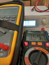
IMG_20210123_111704939_HDR.jpg

Meter on the right is the output of the supply measured from the front terminals of the supply. It is about 3 inches of wire from the power supply, but no current is flowing through that path, instead the current flows through about 10-12 inches of wire to the "high current" outputs on the back. The meter on the left shows the voltage measured at the cell terminals. You can see from the power supply and meter, the power supply is now in constant voltage mode and set for 3.6 volts, 31.5 amps are going into the cell that is at 3.339 volts. The power supply will happily output 40 amps (I have that limit set, since that is the rating) if you keep increasing the voltage. But with the voltage set, and the resistance of the cell and wires, it can transfer 31.5 amps at this moment.
 
Pictures help, I have an example.
View attachment 34680

Meter on the right is the output of the supply measured from the front terminals of the supply. It is about 3 inches of wire from the power supply, but no current is flowing through that path, instead the current flows through about 10-12 inches of wire to the "high current" outputs on the back. The meter on the left shows the voltage measured at the cell terminals. You can see from the power supply and meter, the power supply is now in constant voltage mode and set for 3.6 volts, 31.5 amps are going into the cell that is at 3.339 volts. The power supply will happily output 40 amps (I have that limit set, since that is the rating) if you keep increasing the voltage. But with the voltage set, and the resistance of the cell and wires, it can transfer 31.5 amps at this moment.

Should the difference (3.597-3.339 = 0.258) be interpreted as the result of resistance in the total circuit (wiring/connectors + cell internal resistance)?

And could we derive the resistance of the circuit by:
Vdrop / Current = Resistance
0.258 V / 31.5 A = 0.0081905 Ω

And could we then use that resistance, to calculate the point at which a psu set to 40A and 3.6V would (approximately) switch from CC to CV model:
Resistance x Current = Vdrop
0.0081905 Ω x 40 A = 0.3276 V
and then
3.6 V - 0.3276 V = 3.2724 V

Or am I way off the reservation again :rolleyes:
 
And assume your charger doesn't have voltage sense leads.
If we were to assume the charger did have voltage sense leads how would this change the scenario,

Voltage sense leads would correct for the difference in voltage measured at the power supply and at the cell terminals, in which case the power supply would be able to stay in CC longer and not switch to CV until the cell was at or very near the actual CV setpoint by compensating/adjusting for the voltage drop?
Yes constant current until 3.650000 volts as measured at the battery terminals.
I don't think constant voltage(absorption) makes much sense at that point.
Imagine the charger is like another cell at this point the "cells" are "top balanced".
Leaving the charger on just prevents the cell from settling which is unnecessary stress.
 
Last edited:
Should the difference (3.597-3.339 = 0.258) be interpreted as the result of resistance in the total circuit (wiring/connectors + cell internal resistance)?

And could we derive the resistance of the circuit by:
Vdrop / Current = Resistance
0.258 V / 31.5 A = 0.0081905 Ω

And could we then use that resistance, to calculate the point at which a psu set to 40A and 3.6V would (approximately) switch from CC to CV model:
Resistance x Current = Vdrop
0.0081905 Ω x 40 A = 0.3276 V
and then
3.6 V - 0.3276 V = 3.2724 V

Or am I way off the reservation again :rolleyes:
That sounds about right to me. Of course I haven't really done calculations like that in 35 years. The. 008 ohms value is certainly in the right ballpark. I can also say that the 3.27 volts value for switching out of constant current sounds correct as well.
 
  • Like
Reactions: Dzl
Yes constant current until 3.650000 volts as measured at the battery terminals.
I don't think constant voltage(absorption) makes much sense at that point.
Imagine the charger is like another cell at this point the "cells" are balanced.
Leaving the charger on just prevents the cell from settling which is unnecessary stress.
Yes, you and DZL grok the subject.
Sometimes I feel like I am back in 4th or 5th grade trying to explain why it is perfectly fine for your 40 amp supply to only be putting out 20 or 30 amps (and way less near the end). Teachers used to give us algebra problems, and ask how I knew to solve them, my truthful answer was "it just seemed right".
Truth is, if you tweak the voltage to continue putting out 40 amps, sooner or later you will bloat a cell because the voltage rises so quickly at the end.

Obviously sense leads and an intelligent charger that turns off the charge would work well, but with a human involved all bets are off.
 
Last edited:
  • Like
Reactions: Dzl
Yes, you and DZL grok the subject.
Sometimes I feel like I am back in 4th or 5th grade trying to explain why it is perfectly fine for your 40 amp supply to only be putting out 20 or 30 amps (and way less near the end). Teachers used to give us algebra problems, and ask how I knew to solve them, my truthful answer was "it just seemed right".
Haha, this was basically my approach as well.. bass-ackwards, inside-out, round-a-bout only semi-articulable but arriving at the right place mostly.
Not coincidentally, that's what I did above, played around with the numbers until it felt right and I could almost-kinda-semi-coherently explain why.

Obviously sense leads and an intelligent charger that turns off the charger would work well, but with a human involved all bets are off.
After this discussion I'm wondering why sense leads are not a standard feature.
 
Should the difference (3.597-3.339 = 0.258) be interpreted as the result of resistance in the total circuit (wiring/connectors + cell internal resistance)?

And could we derive the resistance of the circuit by:
Vdrop / Current = Resistance
0.258 V / 31.5 A = 0.0081905 Ω

And could we then use that resistance, to calculate the point at which a psu set to 40A and 3.6V would (approximately) switch from CC to CV model:
Resistance x Current = Vdrop
0.0081905 Ω x 40 A = 0.3276 V
and then
3.6 V - 0.3276 V = 3.2724 V

Or am I way off the reservation again :rolleyes:
Cell internal resistance is not part of the voltage drop seen here. Otherwise your math is fine.
 
  • Like
Reactions: Dzl
Haha, this was basically my approach as well.. bass-ackwards, inside-out, round-a-bout only semi-articulable but arriving at the right place mostly.
Not coincidentally, that's what I did above, played around with the numbers until it felt right and I could almost-kinda-semi-coherently explain why.


After this discussion I'm wondering why sense leads are not a standard feature.
Sense leads and the ability for the supply to use them costs extra.
 
My $7000 msrp (not what I paid) HP boat anchor power supplies have sense terminals.
Fairly common on mid-range supplies too.
That would do a good job of zeroing wire harness resistance.


Something like this would do well - 6V 180A, 20V 76A, or whatever range you plan to use.


Current model, price for a commercial operation not us hackers.

 
@Dzl You've probably heard me talk many times about using off-the-shelf CC power supplies to charge cells. Lets step through each stage and I'll describe what's happening and why.

Three things you have to keep in mind:

1. A LFP cells internal resistance goes up as its charge state goes up. This is initially a minor contributor but it does have a noticible effect near the end of the charge cycle.
2. A constant current limiting power supply reduces its output voltage to control how many amps its putting out so it doesnt overamp itself and melt.
3. Amperage is governed by how much 'force' (voltage) is pushing and how much resistance there is inhibiting that flow of amperage. Loads aren't 'pushed' power, loads 'pull' power based on its resistance and how much voltage there is to move the amps along. You could have a power source capable of a million amps but a load is only going to pull what it pulls.

Stage 1
LFP cell is at 2.50V, power supply is set for 3.65V giving us a 1.15V difference to move amperage.
Cell is connected and amps begin to flow, there are a dozen or so millohms total resistance in cell, cables and connectors but not enough to prevent a huge flood of amperage - WAY more than the PS can handle. Power supply detects this overload and reduces its output voltage to 3.1ish volts (bringing down the voltage difference to .6v) to throttle back the amount of amperage the cell is pulling from it to what the PS can handle.

Stage 2
As the cell voltage rises the voltage differential goes down and so the resulting amperage goes down, the PS knowing its supposed to be putting out 3.65v (but it's not because it's in a overload condition) raises its voltage up (thus allowing more amps) until it hits its overload limits again with the net effect that the amperage stays the same but the PS voltage raises with the cell voltage keeping the original voltage differential it had to keep from overamping. -------This is the Constant Current stage of charging.

Stage 3
The cell voltage has raised enough that the power supply can now output the 3.65v it was set for without overamping. It does a little happy dance. The cell voltage keeps rising thus the voltage differential starts decreasing which means there isnt as much voltage available to move the amps along so amperage starts dropping ----------This is the Constant Voltage stage of charging

Note: If you were really in a hurry you could raise the set voltage some more to maintain the voltage differential you've had all along to keep the amperage flowing at the maximum rate. This is what a "quick/smart" charger does but it's not necessary, it just shaves off overall charging time.

Stage 4
Amperage continues to drop and the voltage differential gets lower and lower. Because the voltage differential is so low now the resistance of the cells (which has gone up), cable, and connectors is inhibiting amperage flow to a greater and greater degree since the ratio of voltage to resistance is tipping in favor of the resistance. Eventually amperage drops to just an amp or less, getting less and less as time goes on. Amperage changes are fairly slow at this point but eventually amperage goes to almost nothing as resistance triumphs over the very little differential voltage available. --------- This can be considered the Absorption stage of charging

Stage 5
Amps leak from positive to neg inside the cell, microscopically dropping the cell voltage to allow more amperage in. Big player in lead acid batteries but almost zero in a LFP cell. ---------This is the Float stage of charging.
You REALLY don't want to do this to a LFP cell, the continued applied voltage is still slowly moving lithium around inside the cell and plating lithium metal to places you don't want it to be and reducing the anode (cathode? can't remember) surface are and permanently reducing the cell capacity.

Hope this made sense.
P1030993.JPG
 
Last edited:
And.... here you go

Power supply + Charge controller = Battery charger

on a side note, I bought the same inverter about a week ago. I had that 500watt thing running 760 watts for about 20 minutes. Never got over 80° when it was 70° outside


diy solar

diy solar
Back
Top