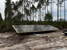
Hey folks, I've got 20 300w panels about 50ft from my EG4 6500ex inverter (which is connected to 6 of the EG4 batteries in a rack). I'm ready to connect the panels to the inverter, but I'm unsure of the best way to wire my panels up. Series or parallel? Do I need a combiner box if my voltage/wattage is within the inverter's limits? And what gauge should I use for this setup to make a 50ft run?
These are the cables I was planning to use: https://signaturesolar.com/pv-wire-100-ft-10-gauge-copper-30-amp-black-red/
Do I just plug each panel into the panel next to it and then the final panel into this longer wire and then directly into my inverter's pv inputs? Seems too easy...
These are the cables I was planning to use: https://signaturesolar.com/pv-wire-100-ft-10-gauge-copper-30-amp-black-red/
Do I just plug each panel into the panel next to it and then the final panel into this longer wire and then directly into my inverter's pv inputs? Seems too easy...