


I'm looking for some wiring advice from you electrician types or skilled Will Prowse types out here.
Backstory:
I am new and interested in going DIY Solar. Sorry for the long back story, but figures it may give some clues. I've built a off-grid 24v (8)272AH pack with 200A BMS and 3000W PSW stand alone with 4 panels. So just got feet a little wet. System works well for the shed and detaches panels for a roller crash cart setup. Recently made Apexium DIY 200A BMS w/16 280AH cells and love it.
Looking for direction:
Now I've got 4 brand new SRNE hybrid HYP4850U100-H all in one inverters which each one has dual MPPT inputs (**reply from Zwy pointed out these units only have one MPPT). My next plan is to begin to plan a solar array that can take my whole house off-grid via the use of a separate load center. I have 200A CH load center today. I want to install about 32 620W bifacial Evo5N panels within 100' from the house on my acreage in Texas. I haven't purchased the panels yet, but leaning into the idea and want to make sure I understand what the wiring is going to look like. Years ago I've rewired a pre-1900's home from 60 fuse panel to 200A service so I did lots of reference to code recommendations at the time. Electricity doesn't scare me, but I do have a health respect for it, and try to lean into safety with proper fusing and wire sizing methodology.
My question stems from lack of experience in the solar field and understanding all the ins and outs of proper wiring techniques as it relates to the whole AC / DC, Solar, latest codes, etc. I'd like to have the solar panels in8 sets of 4 series strings (edited due to reply and changed to different panel selection) 4 sets of 10 series strings up on tilted above ground mount which I'll fabricate. I'll attach the two key pdfs (solar panel and SRNE hybrid inverter AIO) so you can see the specs. I would like advice on best way to optimize solar output using the 4 inverters paralleled (2 in series producing 10kwh to each separate phase of 120v leg in my new 200A Square D main panel. I'll move over circuits as needed. eventually getting each one off-grid. I'll tie ground wire to house ground main panel, and the pv + and - are of course not tied to ground. Just the SPD has its own separate ground rod Skipping this per more research (1 for all SPDs at solar panels) solely for grounding lightning / sudden surge, as I understand it (*and per Mike Holt
, not having a duplicate shared ground!). Feel free to correct me along the way if any of this sounds off.
Some items I've ordered to this end:
(5 6) SPD DC 1000V 20KA-40KA surge protector, low-voltage arrester device for the 8 4 strings of PV (in metal box at panels)
(5 4) 2P DC MCB 1000V 25A - one for each of the 4PV strings into the MPPTs
(4) 1P+N 230vac Residual current circuit breaker with over and short (RCBO) to feed into the main panel (each going into a Square D main's 2p 1phase 120v 60A breaker (is this even necessary since there is an appropriate breaker at the mains input wiring terminal?) that would be two on right side of the panel for phase 1, and two on left for phase 2.
(4) 100V 60A Din rail Dual display Adj. Over Voltage Current and Under Voltage protective device. between each inverter and the Main panel.
*+ (4) 4P Rotary DC Solar Disconnects (2 strings per) at array and (2 at) inverter
+ (4) Arc Fault Detection Devices
Does this sound about right? Am I being silly on any of this? I know some people use combiner boxes and fewer runs, which with the price of copper cabling may be tempting, but I really want to have some solid redundancy in this setup and try to keep lots of flexibility in future upgrades, and so on.
What wiring tips do you have on this, where do I have this all wrong? What am I overlooking? Absurdities?
Backstory:
I am new and interested in going DIY Solar. Sorry for the long back story, but figures it may give some clues. I've built a off-grid 24v (8)272AH pack with 200A BMS and 3000W PSW stand alone with 4 panels. So just got feet a little wet. System works well for the shed and detaches panels for a roller crash cart setup. Recently made Apexium DIY 200A BMS w/16 280AH cells and love it.
Looking for direction:
Now I've got 4 brand new SRNE hybrid HYP4850U100-H all in one inverters which each one has dual MPPT inputs (**reply from Zwy pointed out these units only have one MPPT). My next plan is to begin to plan a solar array that can take my whole house off-grid via the use of a separate load center. I have 200A CH load center today. I want to install about 32 620W bifacial Evo5N panels within 100' from the house on my acreage in Texas. I haven't purchased the panels yet, but leaning into the idea and want to make sure I understand what the wiring is going to look like. Years ago I've rewired a pre-1900's home from 60 fuse panel to 200A service so I did lots of reference to code recommendations at the time. Electricity doesn't scare me, but I do have a health respect for it, and try to lean into safety with proper fusing and wire sizing methodology.
My question stems from lack of experience in the solar field and understanding all the ins and outs of proper wiring techniques as it relates to the whole AC / DC, Solar, latest codes, etc. I'd like to have the solar panels in
Some items I've ordered to this end:
(
(
(4) 1P+N 230vac Residual current circuit breaker with over and short (RCBO) to feed into the main panel (each going into a Square D main's 2p 1phase 120v 60A breaker (is this even necessary since there is an appropriate breaker at the mains input wiring terminal?) that would be two on right side of the panel for phase 1, and two on left for phase 2.
(4) 100V 60A Din rail Dual display Adj. Over Voltage Current and Under Voltage protective device. between each inverter and the Main panel.
*+ (4) 4P Rotary DC Solar Disconnects (2 strings per) at array and (2 at) inverter
+ (4) Arc Fault Detection Devices
Does this sound about right? Am I being silly on any of this? I know some people use combiner boxes and fewer runs, which with the price of copper cabling may be tempting, but I really want to have some solid redundancy in this setup and try to keep lots of flexibility in future upgrades, and so on.
What wiring tips do you have on this, where do I have this all wrong? What am I overlooking? Absurdities?
Attachments
-
Evo 5N N-type TOPCon 156 Half Cells 610-630W.pdf1.6 MB · Views: 0
-
SRNE_HYP series_48V_5kW_Solar storage inverter_User manual_V2.2.pdf3.4 MB · Views: 3
-
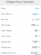 DCVoltageDrop-8AWG-100ft.png26.6 KB · Views: 4
 -
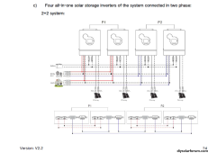 SRNE-Parallel2+2Config.png164.2 KB · Views: 4
 -
Evo6 Series 120 Half Cells Bifacial Dual Glass 590-620W 1201.pdf250.6 KB · Views: 1
Last edited:


