diy solar

diy solar

Wiring two banks (4 each) of SOK server rack batteries together

jeremyhanks

New Member
Joined
Oct 8, 2022
Messages
3
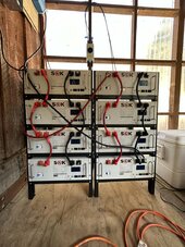
What is the appropriate way to wire these two banks of four SOK batteries together?

Right now, I just have the bank on the right running to my Victron Lynx Shunt with equal length +/- cables.

I just got the second bank of 4 up and running, so new problem.

I've tried deconstructing the Victron Wiring Unlimited document, but not exactly sure how to apply it with two banks setup like this with the short wires connect each four together in parallel.
 

Attachments

  • IMG_5004.jpg
    IMG_5004.jpg
    215.8 KB · Views: 10
I believe you could connect the positive from the left top battery to the positive of the right top battery
and the negative from the left top battery to the negative of the right top battery.
This would be equivalent in having all eight batteries in parallel
Connect the inverter positive to the left bottom positive and the inverter negative to the right bottom negative

By the way you could connect the battery to battery communication cables between RS485B and RS485C from battery to battery. B to B or B to C, doesn't matter.

With one bottom battery address set to 1 and all others sequentially addressed you would be able to monitor all batteries using the SOKTools.exe which you can download from Current Connected by using an RS232 to USB cable plugged into the RS232 (smaller RJ12 jack) on the battery with address set to one. You do not have to connect the master battery to the inverter. in Addition Solar Assistant could then monitor all eight batteries instead of a computer

This is the RS323 to USB cable I use for my SunGoldPower batteries (SOK Clones)


Probably ok, but only if the inverters don't draw more than the capacity of the wire.

Downside is the SOC of the batteries will get out of whack. With 8 in parallel I would bet the middle 2 don't get charged or discharged more than 30% while the ends get 80% or so.

Read this to see what and why I say that.


Were it me I would add 6 bus bars. Long ones for each set of 4 batteries and short ones to combine the two. For the long ones just hook like the say in post #4. Then those to either end of the short pair and from the middle to the inverters
 
You have a few options available to you.
1) Wire each pack to a common DC Bus in parallel.
2) Wire each set of 4 to a common DC Bus. Linking 4 packs as you have done per rack and routing each rack to a BUS. This could allow for a Switch for Bank 1 & 2 or both Combined
3) Link both racks by continuing the "daisy" chaining and having only 1 set cables going to the Lynx.
Linx Box can take a 4 inputs. You could wire both racks to it OR the combined Rack 1 & 2.

The GOTCHAS
#1) allows for interconnection (RS/CanBus) but a LOT of wire which has to match in length and getting another lynx to handle all 8. PITA Setup.
#2) This would need 2 connections to Lynx. RS/CanBus can still be linked up no issues. Using a switch can allow isolation of either bank. OPTIONAL depends on your use case & fault tolerance setup.
#3) Best Option. This is KISS Applied which is ALWAYS BEST ! This does require Care & "Perfection" when it comes to wiring. The little things show up in a bigger bank config. See below

CRITICAL !!! The Cables running from the combined racks MUST be exactly the same length, Guage also has to be large enough to minimize Line Loss & Resistance and of course handle the Max Amps POSSIBLE (worst case / max load) that can be drawn. I Very Strongly suggest that you use High Quality wire with ultra-fine copper wire and premium tinned copper terminals. NO Exposed Copper ! (Asking for Murphy's laws to be applied)

2) Just as you have Daisy Chained 1 Rack you continue that across with longer "bridge" cables in the same sequence. My strong suggestion for this is to step up to the next largest Gauge to compensate for the extra length because they will be longer than the default ones provided. NOTE: The wires provided by SOK are Ultra-Fine copper wire. Some of these interconnect battery cables are also Premium Silicone wire which can handle more amperage. I would continue with that if that is what they provided, you can tell just by the feel and markings if visible.

3) The Daisy Chain. Your 1st rack is correct, taking (+) from 1 side with the (-) from the other side of the chain is the correct way to do that. This would be the same except that you link the two racks with bridge cables.

I did not see any of the RS/CanBus communications ports wired up. The battery packs can interoperate with each other and pending on your inverter-charging systems with that as well. Additionally they can be managed by the software "as an entity" with a few quirks to get around. SOK does support Victron Comms (quite well from what I know) and that has a LOT of value for monitoring, management & tweaking to optimize.

The MOST IMPORTANT ADVICE - Keep It Sweet & Simple is the GOLDEN RULE. More complicated, more connections and bits ALL add to "little things" in the same sense as "death by a thousand cuts" as the little things pile on. BTW, it doesn't take long to pile on either !

Hope it helps, Good Luck.
 
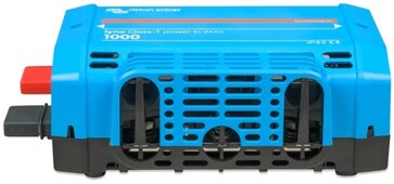
Potential option, still on preorder looks like June delivery.

Class T power in (be aware this is using m10 bolts not m8s). Would give you one class t fuse per bank (use two 400A fuses).

You'll need to drill the holes out on the lynx shunt (usually m8 sized) to get them to fit together:

Screenshot_20240422_080931_Gallery.jpg
 
Back
Top