Thanks that makes sense now, I was misunderstanding what you meant. Now I see.This piece was cut in the "X" direction to show how well squished the braid was.
Now cut it in the "Y" direction on both edges, removing the copper sheetmetal (flattened tube edges) that hold top and bottom together.
That way, only any bond of sheet metal to braid, braid to braid, and braid to copper holds the sandwich together.
Does it fall apart? Does it resist light or heavy tugging?
On that point though, how significant of a factor would that be?
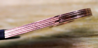
Referring back to the CALB busbars (closeup), they are just thin stacked copper strips, and seem to have stood the test of time, with no more compression than heat shrink + bolt fastening them to the cell terminal.