These braided ones that I make are rated for 150A. They're 25mm2 (25mm wide x 2mm thick) - maybe this helps as a reference.
You are using an out of date browser. It may not display this or other websites correctly.
You should upgrade or use an alternative browser.
You should upgrade or use an alternative browser.
Best practice for 300kgf ‘fixture’ 280Ah cells
- Thread starter fafrd
- Start date
Everyone keeps referencing 300Kgf and 661Lbf, but what I really want to know is how many Stones force we are talking.
My guess is simplicity (as in its just a piece of copper, its cheap, and they usually come with the cells)
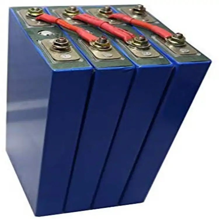
Short, large AWG cable seems common for connecting a bunch of LA batteries, but with the high number of cells and very short distance between cells, large gauge wire seems like more trouble than flat bars, braided busbars, or the CALB style busbars (which I think are a balance between simplicity, cost, and tolerance)
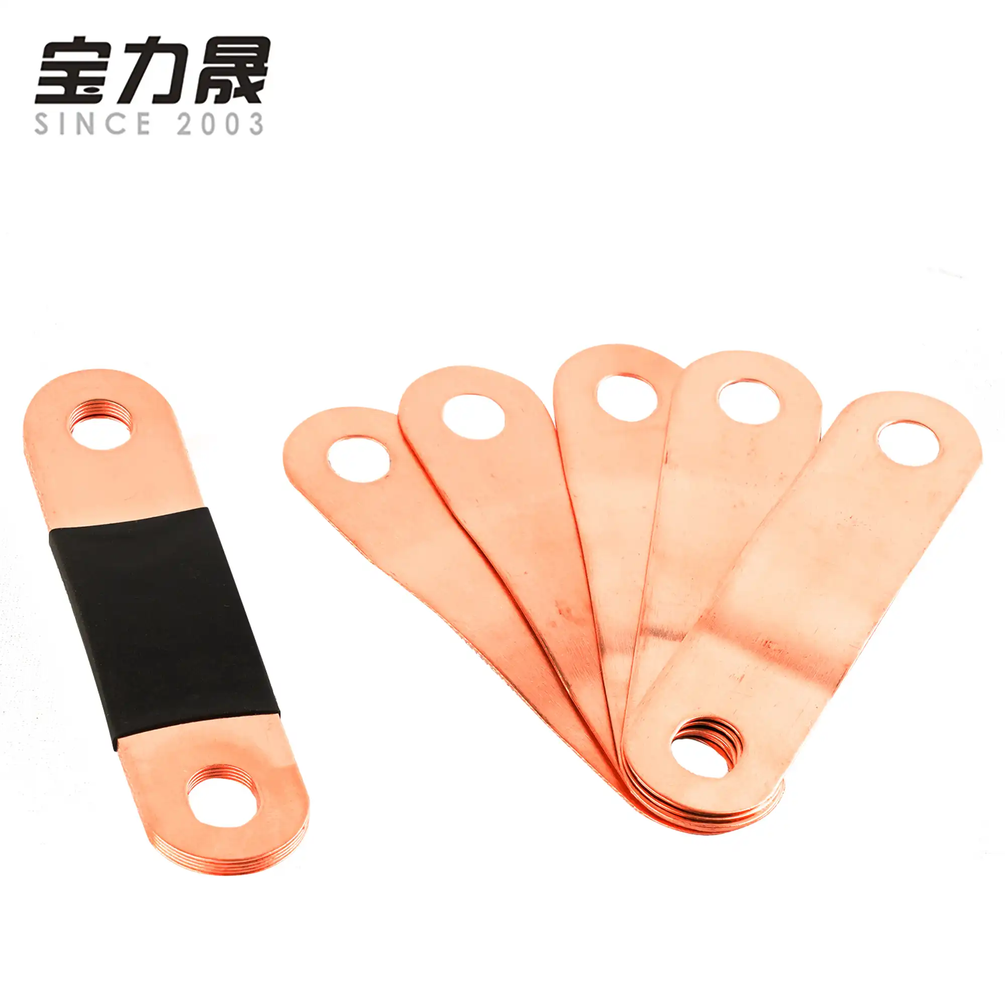
This is a CALB style busbar:
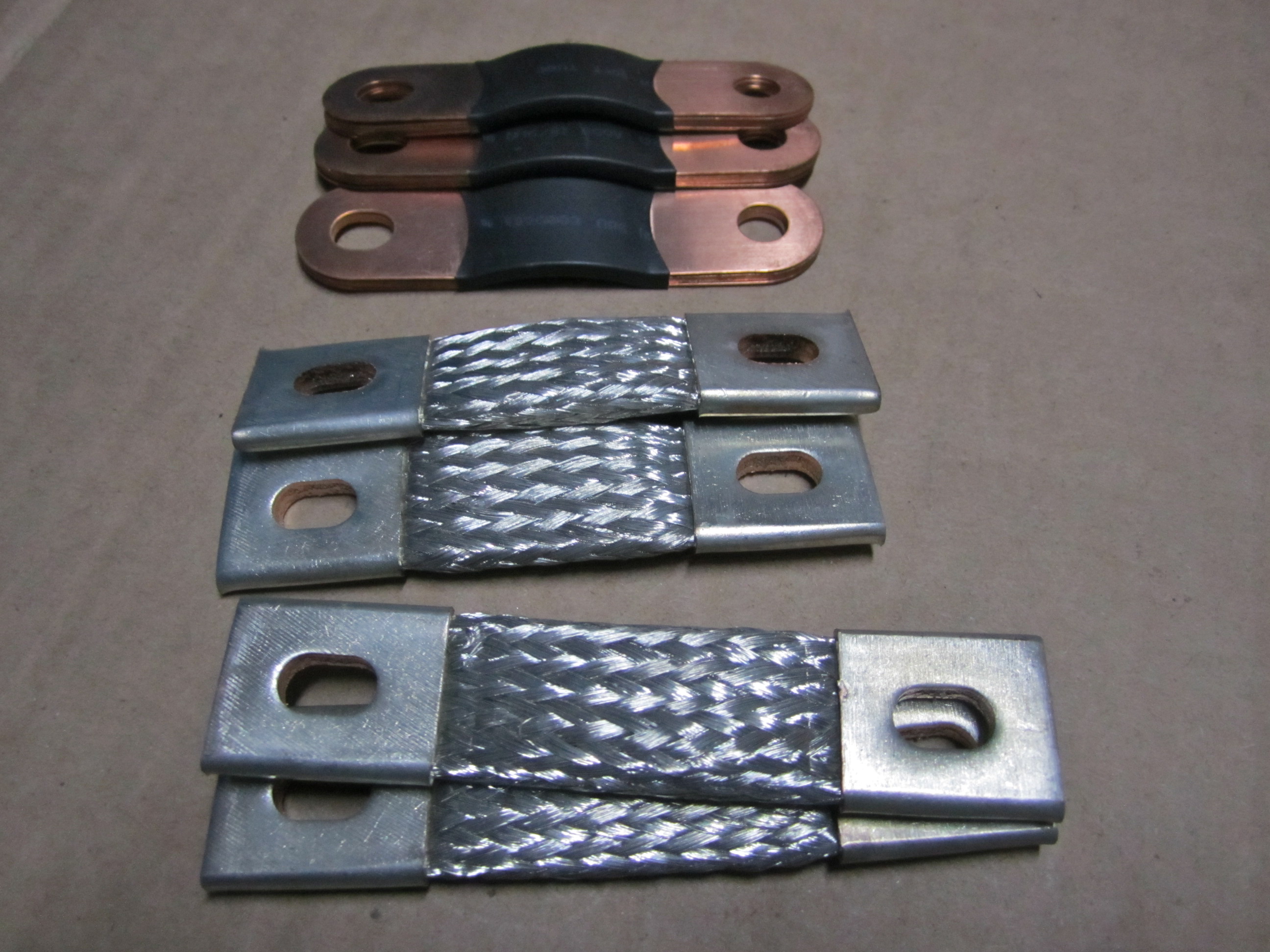
The left and the right are the same thing (the right side is just deconstructed) the CALB bars are many thin layers with some curvature to allow some small amount of flexing/expansion.
Here are CALB style busbars next to some very high quality looking braided bars.
And here is an example (I think, its hard to tell) of using wire instead of busbars as you suggest:

I totally agree with everything you said except one point. A couple of my cells are diluted and there is isn't any space at the ends of the busbars. They reach but just barely. I noticed this when I parallel top balanced. When I get around to reassembling the pack, I hope to make it more square.
I am not at all concerned about increasing cycle life because my cells are going to be used for back up in the event of a power failure. I will cycle them probably monthly. My only concern is preventing stress on the terminals.
This battery stuff is complicated but I am trying to keep it as simple as possible and stay away from the weeds....in other words not trying to be absolutely perfect...lol.
not sure what you mean by ‘diluted’ but if damage to terminals from swelling (and stress from solid busbars) is your highest priority, going to the trouble of making 7 (or whatever S - 1 is) short wires with appropriately-sized lugs on either end is probably the safest route.
Then connect diagonally rather than straight which has the advantages of:
1/ even more flexibility / give in the face of cell swelling
2/ cells are all oriented front-to-back meaning swelling should ‘spoon’ just like lovers in bed
Hedges
I See Electromagnetic Fields!
- Joined
- Mar 28, 2020
- Messages
- 20,710
These braided ones that I make are rated for 150A. They're 25mm2 (25mm wide x 2mm thick) - maybe this helps as a reference.
25mm x 2mm = 25mm^2 ?
Let me clarify, they are nominal 25mm^2 but because they are braided, this is the equivalent of having two layers in the braid, making the braid 25mm x 2mm.25mm x 2mm = 25mm^2 ?
Hedges
I See Electromagnetic Fields!
- Joined
- Mar 28, 2020
- Messages
- 20,710
Not cheap at all.
I paid same price for 10" 4/0 cables with ring terminals crimped on and glued heatshrink.
I am not the most learn-ed fellow when it comes to the complexities of current and AC vs DC and ampacity, but i'm also not the least learn-ed. From what I recall, issues with thin strands are an AC thing, not a DC thing, and even with AC they are most pronounced at high voltage.I thought that stranded copper was a poorer conductor, but have also read somewhere that this is incorrect?
One other thing I recall is that there are different opinions and understandings on this from folks more informed than me, so don't be surprised if 4 people respond with 5 opinions
What I think was agreed upon, its a non-issue for low voltage DC.
As a reference point, the marine code mandates using stranded or fine stranded copper conductors for all wiring (including AC)
Last edited:
So here is the thing I visualize. Others may disagree with me but I have found disagreements are good because I learn something new.Yes I agree with this assertion. I still wonder though what the genus for solid bus bars is?
I thought that stranded copper was a poorer conductor, but have also read somewhere that this is incorrect?
Your thoughts or knowledge please? 'Cause I think this guy is looking at cable bus vs. solid to eliminate issues with swelling and terminals.
The cells do expand and contract when charged and discharged. I have sat here and watched it for myself. I like to use the word expand as opposed to swelling. I associate swelling with over charged cells.
Since they expand and contract, my own belief is by using something flexible between the cells for interconnects is the only way to prevent stress to the terminals whether they are compressed or not. For the near term personally I am not concerned. Long term usage is what I am concerned about.
There may be cheaper options, that's just the first I found.Not cheap at all.
I paid same price for 10" 4/0 cables with ring terminals crimped on and glued heatshrink.
The braid itself is fairly cheap: https://www.gacopper.com/Braid.html if you want to go @upnorthandpersonal's DIY route.
Hedges
I See Electromagnetic Fields!
- Joined
- Mar 28, 2020
- Messages
- 20,710
There may be cheaper options, that's just the first I found.
The braid itself is fairly cheap: https://www.gacopper.com/Braid.html if you want to go @upnorthandpersonal's DIY route.
What I wonder is how intimate contact between braid and terminals is maintained.
Round crimp on stranded wire is shrunk slightly in area, supposed to achieve cold weld.
My guess is these braid terminals rely on the relatively modest pressure from torqueing 6mm or 8mm screws in aluminum cell terminals.
Maybe that is sufficient - that's also all the force the contact gets.
@Hedges, I have a picture of that from one of mine. It's a cold weld (done with a hydraulic vise preferably).
Diluted like this.not sure what you mean by ‘diluted’ but if damage to terminals from swelling (and stress from solid busbars) is your highest priority, going to the trouble of making 7 (or whatever S - 1 is) short wires with appropriately-sized lugs on either end is probably the safest route.
Well there you go. I had forgotten about going with diagonal configuration and I thank Dzl for that photo and your insight into this. I thank both of you and I will look at it when I redo the pack. I think it's a great idea.if damage to terminals from swelling (and stress from solid busbars) is your highest priority, going to the trouble of making 7 (or whatever S - 1 is) short wires with appropriately-sized lugs on either end is probably the safest route.
Then connect diagonally rather than straight which has the advantages of:
1/ even more flexibility / give in the face of cell swelling
2/ cells are all oriented front-to-back meaning swelling should ‘spoon’ just like lovers in bed(meaning less overall and more uniform pack swelling than when cells are oriented back-to-back and front-to-front).
Hedges
I See Electromagnetic Fields!
- Joined
- Mar 28, 2020
- Messages
- 20,710
@Hedges, I have a picture of that from one of mine. It's a cold weld (done with a hydraulic vise preferably).
You describe it as "cold welded".
Still got that X-sectioned sample? How about cutting off the flattened edges, see it it is actually a metallurgical bond?
Cold welding - Wikipedia
I have a suspicion this process is behind some sticking relays I encountered. Such low current flow they were never burned or pitted at all, just planarized by light tapping until surface area of contact was able to bond and overcome the spring. Or maybe "sticktion"?
Stiction - Wikipedia
@Hedges I don't follow what you are asking him to cut? The outer long edges? Is that likely to have a meaningful impact for our usage (honest question, the complexiities of this are over my head)?
Reposting @upnorthandpersonal 's pictures from the other thread so we don't have to keep flipping between threads (and also for the general sexiness of the finished product ):
):


Reposting @upnorthandpersonal 's pictures from the other thread so we don't have to keep flipping between threads (and also for the general sexiness of the finished product
It will add length but if using a large enough awg it shouldn't matter?I like that diagonal idea too .... that would take a lot of pressure off the terminal. I will add quite a bit of length to the bus connections, however.
Hedges
I See Electromagnetic Fields!
- Joined
- Mar 28, 2020
- Messages
- 20,710
@Hedges I don't follow what you are asking him to cut? The outer long edges? Is that likely to have a meaningful impact for our usage (honest question, the complexiities of this are over my head)?

Asking to determine if any "cold weld" has in fact occurred.
This piece was cut in the "X" direction to show how well squished the braid was.
Now cut it in the "Y" direction on both edges, removing the copper sheetmetal (flattened tube edges) that hold top and bottom together.
That way, only any bond of sheet metal to braid, braid to braid, and braid to copper holds the sandwich together.
Does it fall apart? Does it resist light or heavy tugging?
The busbars are what, 20mm^2.I like that diagonal idea too .... that would take a lot of pressure off the terminal. I will add quite a bit of length to the bus connections, however.
That’s under 4AWG and even if you double up, that’s under 1AWG.
Going diagonally may triple the length but if you just move up to 2/0 or 4/0 AWG you should have roughly equivalent resistance...
Hedges
I See Electromagnetic Fields!
- Joined
- Mar 28, 2020
- Messages
- 20,710
It will add length but if using a large enough awg it shouldn't matter?
All that matters is resistance, which will be proportional to Length/CrossSection or Length/(Width x Height)
Beyond that, the 3-D model of how current crowds into terminal is something I avoid addressing. I find 1-dimensional models so much easier to comprehend and calculate. Most of my electrical and thermal work is done that way.
Similar threads
- Replies
- 1
- Views
- 224
- Replies
- 7
- Views
- 650
- Replies
- 2
- Views
- 241
- Replies
- 4
- Views
- 468


