diy solar

diy solar

Adding storage to my Enphase system

My setup will be the opposite. "IF" all goes to plan... I hope to have a bit over 2,000 watts of solar with the DC charge controller to my battery bank. That should produce something like 10 KWH's a day for me to use at night when the sun goes down. Only 1 conversion from DC to AC in the evening. My current choice is 9 x 300 watt panels, 2,700 watts theoretical peak power. Into a 50 volt battery bank that would be 54 amps, and ramping down as the voltage climbs to 57.4 maximum. So the MPPT 60-150 can take all of the current, and I can get that one for $495 right now. The 150 volt rating is a peak, they recommend staying under 140 volts. Typical 300 watt panels are 60 cell with a VOC of about 38 volts, x 3 = 114 volts, so that looks good. The 3 strings in parallel pushes the current up to just under 30 amps. Not too bad, I will run #8 awg from the combiner to the charge controller. Charge controller to battery bank will need to be #4 or so for 60 amps, I may just step it up to #2 as the cost for my short run will not be a big deal.

So while the sun is shining, the house will run completely off of the existing 4,800 watts of panels on the Enphase iQ7 microinverters. But all of the excess power will pretty much go back to the grid. The system is not really smart enough to self adjust the charge current from AC coupled solar. That is a shame, as the hardware could do it, but the software is lacking. Schneider did put "Smart Charge" in the smaller SW inverter/charger but it looks like that never made it to the US market either. So with this plan, the XW-Pro inverter will basically just sit idle, as long as the solar from the Enphase system is meeting the house demand. And the charge controller, will be charging the battery bank in the background. As the sun starts to go down, the Enphase will no longer be producing enough to run the house, so the XW-Pro will start running in grid support. I will probably also add the Watt-Node grid meter to the Schneider system, so it can do true Grid Zero mode at this point. It will ramp the XW-Pro output to hold the grid current at zero. The house will then be running off the batteries, and any solar still coming in until complete sunset, then it is on all battery. It should run in Grid Zero until after midnight at which point it will switch back to grid until the sun come sup to do it all over again.

I am thinking of tying in my extra 600 watt charger, and have that kick on if the grid sell from the Enphase exceeds 1,000 watts. I have a few ideas how I could make that work. If I do add all of the cells I bought, I would end up at about 36 KWH's of battery. I could basically go off grid with that much storage, but I would need a bit more charging power. A second 600 watt charger running off the Enphase power would probably do it. It is just a shame that the XW-Pro can't be told to switch to charge mode while on grid, unless the battery is fully discharged below the inverter cut off voltage. It's a dumb software choice.
 
@Hedges
No double conversion 48v
The SSC in the hybrid will produce DC.
This is either converted to AC, or stepped down Battery pack voltage.

It's not directly usable as AC.
That's what makes the IQ7 special.
:)

SCC, 150v, is realistic 160v.
The mosfets are standard 160v seldom 150v, and even if, quality has 10% margine.

The maximal voltage shown on the solar panels is absolute maximum.
That makes it usually safe to use 3 in Series.

SCC does have little better rates with (roughly) double voltage of battery, this goes for all MPPT.
0.5% or so.

Higher amperage is usually higher purchase price.
To be sure, contact your SCC company and ask their opinion about the 3 panels.

For the 2 different packs being mobile, that's a good idea.

As they are in parallel, each need own BMS, they always have the same SOC.

Disconnect them and place both on different location, no balancing is needed.

If you take only one, yes, it needs to get same SOC as the pack that stayed at home.

For LiFePO4 there are only 2 numbers available.
(That give real information about SOC)
2.0 (often 2.5v is used) and 3.65v per cell.

All other voltages are vague indication about possible SOC with easy 15-20% error rate.

Disconnect at 2.2v with 10A load will recover to 2.7-2.9v in a few hours.
You will need to run several discharge cycles to end up with 2.5v.

Stop charge at 3.65 will reduce to 3.38-3.45 in a few hours, you will need continuous charge for several hours to 3.65 (or close to) to have end voltage that stays 3.6 for a few days.

Only with those 2 numbers the cells are (almost) equally empty or full SOC.

If you want to reconnect, both packs need to be fully charged or empty.
No road in-between.

Also, not really balancing, as it's normal way of working, the same as you (hopefully) are planning to do when connecting the new to buy pack....

9 kWh, 180Ah cells, about 3kg each.
The pack will be roughly 50kg.
Cells need to be compressed to avoid delamination (bloating)
And casing strong enough to be carried.
Should be possible under 60kg.

Better move around with 2 people :)
Even if you are sports guy, moving 60kg gentle and careful can be challenging.

Sounds like a good plan!!
 
Last edited:
I just got my electric bill for May-June. I still managed a net negative energy usage, but just barely. The non bypassable charges ate up all my credit from the negative power use, so I owe $6.30 now. Not bad for 3 full months of power. If this weather holds up, I will likely be in for more like $25 next month. This heat is unreal.
 
If you want to reconnect, both packs need to be fully charged or empty.
No road in-between.

Are you sure?

Not that I use lithium, but here is my reasoning:
What if two partially charged battery packs are at say 50% and 70%, and you put a resistor between them bringing them to same voltage, then connect in parallel.
Start charging. After a while, the one that was 70% will reach the knee but voltage is kept from rising more by the one that was 50%.
So the more full pack has to wait for the other to catch up. Only then does voltage begin to go further up the knee.

Reconnecting and charging these to packs should be no different than paralleling and top-balancing two cells.
 
The batteries I am using are Li NMC cells from a Chevy Bolt. My current pack is 6P14S of 60 amp hour cells. Their voltage curve is a much more linear slope than LFP so state of charge to voltage is a bit more realistic, but still not perfect of course. The original pack is using a JK BMS with active balancing, and the cells are holding such good balance that it almost never kick in. I checked right now and the highest to lowest cell is within 4 mv (yes 0.004 volts) across all of the cells while putting out about 15 amps. That is all it is taking to run everything in my house right now. That's only about 700 watts. The A/C has cycled off for a bit, but it is still 80F outside right now, so it will kick on again. But without the Watt-Node yet, the XW-Pro inverter will not know so the A/C compressor will actually be taking it's power from the grid.

The Chevy Bolt cells are still in the Chevy/LG Factory cell holders. There is a thin aluminum plate between every pair of cells. The main blocks are 10S. They are wired in 3P groups for 30 cells. I have 2 of those, and one 8S brick with 24 cells. I cut the middle buss bar on the 8S pack and wired each half on the ends of the 10S bricks. So I end up with two 3P14S block is a total 42 cells + 42 cells. Those are run in parallel and tied to one BMS.

I just purchased 3 more 10S bricks, the 8S was not available. I will pull 6 cells out of the middle and splice the two resulting 4S packs onto the end of each 10S complete brick. I think each of these will have their own basic DALY BMS. The cells have proven good enough to not need the active balancing. My old bricks were from 2017 and 2018, obviously from different lots, and matched perfectly, these new ones are dated Nov. 2020. They are new cells, all from the same car. One end of each brick still has the formed steel plate to provide the compression to the cells. On my first set, I used a 1/8 inch thick aluminum plate, and then a steel bar diagonal across the middle, as I did see the center start to bulge out a tiny bit. I am not putting pressure on them, just restraining them from growing. I do not have an accurate weight on them, but carrying one of the 10S groups is not that bad. My original bank is in a roll around rack cabinet. I will probably put each of the new half size banks in a smaller metal case with wheels. At least one will have an inverter in it to be a 9KWH power bank.

As for the balancing to re-connect, it is not too big of a deal. Since I cycle my system from 57.4 down to 51 volts each day, I will just connect it to my system as it comes down to wherever the portable pack was. The charge/discharge curve is quite predictable and easily monitored. If I get them within 0.5 volt, I can connect it through a #4 awg wire as a resistor to pull it in. If they are wildly different, I will use a large 0.1 ohm resistor across the disconnect switch until the current is fairly low. Since these are VE cells that can take huge regen braking, LG rates the to 3C constant discharge, and up to 1C constant charge rate, and 2C burst charge. So the 3P pack could take 180 amps of charge current and 540 amps of discharge current with no damage. And my current 6P pack is double that, but I have it fused at 175 amps, since my inverter tops out at 140 amps. Compared to driving the Chevy Bolt, these batteries are just coasting. My cycle depth would be like driving the car about 120 miles each day, and slow charging them at just a 0.06C rate. When I double the pack up, if I use all 4 strings for 720 amp hours, even with the DC solar charging, I will never exceed 0.2C charge rate. And maxing out my inverter at 6,800 watts would still not exceed a 0.2C discharge rate either. These batteries are so compact and energy dense, it is truly amazing. Compared to LFP, they do have a slight chance of catching fire, but I am following all of the safety rules and never charge them past 90% either. The temp sensors have never shown them to be any warmer than about 1 or 2C above the air temp in my garage. But to be completely honest, the highest I have tested them to yet has been 80 amps on the 360 amp hour bank. I will only go a little higher if I do try to have it zero the grid with my A/C running. The compressor would add another 3,400 watts of load to my normal 1,300 watts during the day, so it does have the capacity to do it within it's rating. It just can't supply the start surge, which will come from the grid.
 
I think you could supply the start surge. My AC unit pulls roughly the same amperage/wattage as yours and I purposely ran the AC when I was doing the grid down test.

My AC unit is nothing special. Looks like a standard 10-15 year old central air unit.
I'm not sure on the size, that label is missing.
(1/4 hp, 77 lra, 13 SEER)

All I did was add a soft starter.
The one I purchased cost a few hundred, but when the power goes out this summer it would be pretty pointless to have this huge heavy inverter and battery bank with huge discharge capacity.


Edit:
Also, do you have this 0.1 ohm resistor? It seems like it would need to dissipate quite a lot of heat.
Say if you connected the packs with a delta of 5 volts. A 0.1 ohm load would be 50 amps. I think it would be at 5 volts, so 250 watts?
Either way, that must be a nice beefy resistor. At at 250 watts of heat times the hours it could take to balance at 50 amps, a very well cooled, beefy resistor.
 
Last edited:
The rating on my A/C compressor is 105 LRA. Once running on the low stage it draws 14 amps at 240 volt. I have not gotten a solid reading on the high stage. The plate says 23 amps, but I doubt it is that high. It does not change the compressor speed, it just closes down the orifice valve which does increase the high side pressure though.

Currently I have a pair of 500 watt 8 ohm resistors. I use them in parallel from time to time for other things. But 4 ohms would take days to balance the two packs. If I can't find a suitable power resistor (or bank of them) I may just resort to using a length of #8 awg wire. But my plan is to have the banks closer than a volt or so before trying to tie them on.

I have not had a chance to cut the one pack open yet. Did you take any pictures as you cut the plastic between the cell groups? It looks like I only need to cut the insert as each pair of cells are already in separate cell holders.
 
105 LRA might be too much even with a soft start, but there's only one way to know.
I haven't measured the starting current after install, I really should.

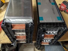
I have this pic that shows both sides of the cut. Basically yes, just cut the center "insert" and circuit board and bus bar. The outer cell holders don't need to be touched.

I haven't yet assembled these 2 packs, let me know if you need more pictures.

PXL_20210418_193107238.jpg
 
That picture s perfect, thanks. I am probably going to pick up an oscillating tool today and try and split on of the blocks this week. Since the two 10S bricks are opposite polarity, I am going to splice the 4S on opposite ends, so the output ends up on the factory GM/LG studs, and my link cable has the clamp connector onto the buss bar. On one pack the negative end will be on the 4S block, while the other pack will have the negative end on the 10S block.

I am not too worried about getting my A/C to start on the inverter, but I may get a soft starter anyways to calm the surge. I found a box by Hyper Engineering. They call theirs the Sure Start. They claim it can drop the LRA by 60%. In theory, that would get it down to 50 amps or so. It's $259 at a few online stores and has great reviews.
 
The unmodified heat pump compressor LRA here is 121A, far over the load rating tor the XW Pro inverter.

However, I put a “Soft Start” kit on the heat pump compressor some years ago, as the 21kw Diesel generator was not happy starting the heat pump either.

Kit worked great, the generator can start & run the heat pump easily, after the modification.
But I have no idea how many amps it takes to start the heat pump now.

LRA is now less than the 87A from the genset, and more than the 50A capacity of the Schneider 6848 inverter.

I am not having any luck finding any test equipment that will measure & record the instant amp spike.
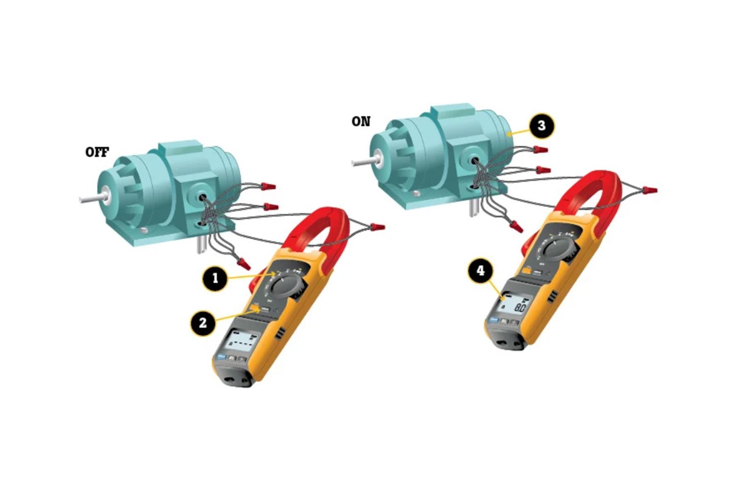
Neither the Fluke amp clamp or the IotaWatt capture the transient event.

Thinking about adding a second XW Pro, that would provide 100A of 240vac for the LRA event.
 
I am not having any luck finding any test equipment that will measure & record the instant amp spike.
Neither the Fluke amp clamp or the IotaWatt capture the transient event.

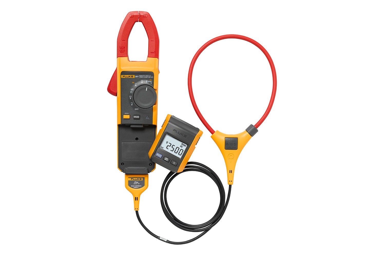
Compact way would be a meter meant for that. Fluke says, "Only meters that offer an inrush button can measure inrush current."


I do it with a current transformer and oscilloscope


Startup of a window air conditioner


Current drawn on AC lines and inverter battery ripple current

 
Thanks very much!
Fluke 381 or 376FC look good, can't wait to see what the heat pump is pulling w/ the soft start !

When I contacted Fluke a few weeks ago, the sales person was unable to answer “Do you have a product that will measure and capture AC inrush current?”
But he did send me a link to safety procedures………
 
Last edited:
I've had a Fluke DMM for two decades and considered one of their clamp meters (despite the price), but resolution and accuracy weren't what I wanted for PV strings.


"
DC Current
Range999.9 A
Resolution0.1 A
Accuracy2% ± 5 digits
"

I bought the HF Ames CM1000A instead. On 60A range, 0.01A resolution
Looks like it does have an "inrush" feature. Don't know how fast, I'll have to compare to my scope.


"Inrush Current Ranges: 60A / 600A / 1000A Frequency Range: 40-400Hz Inrush Integration Time 100mS"
 
It would be amazing if the HF performed to meet it's published specs!
Quite a dramatic $$$ difference, compared w/ the Fluke, especially for a tool that I would only ocasionally use.
 
Yes, I'm hopeful.
It is rather big and chunky compared to the Fluke, but the clamp range is up to 1000A DC.

Just realized I ought to take some direct measurements for comparison. I blew the fuse (again) in my Fluke, need to order replacements.
I remember logging power from my refrigerator a while back. This past weekend, clamp meter showed just 1A when running. I'll see how Fluke (shunt) measurement, Ames clamp measurement, and current transformer compare for AC. For DC I can use my bench supplies with built-in current reading, along with the Fluke.

Ames DC accuracy specs were similar to Fluke and others, a percentage and some counts of LSB. A few more counts (says 8 vs. 5) but on 60A range that's 8 x 0.01A which is much better than 5 x 0.1A of Fluke. I wanted to be able to read a 7A PV string off peak sun when it might produce 1A, and I don't need +/-0.5A error.

"DC Current Ranges: 60A / 600A / 1000A DC Current Accuracy ± 2.0% of rdg + 8D"

Hall-effect sensors have a zero-offset that needs to be cancelled. At work I use a LeCroy scope ($50k?) with a clamp current sensor ($5k), that does degauss and zero. But after I perform a test with 30 ampere turns, it develops a zero offset. Can't measure DC current accurately on account of that, but my primary need is to measure ripple (trying to get measurements down into the ppm range.)

I think the Hall effect work by using sensor to measure magnetic field, then driving a coil of wire to cancel the field. Output of op-amp driving it is used as the signal to be measured. In order to get back to lowest range of scope, besides the DUT I inserted a battery-powered coil with potentiometer adjustment, manually cancelling the 30 ampere turn DC portion.

Using the Ames clamp meter, when first set to DC amps there was some offset. I pushed the "Relative" button which stores reading and subtracts it, but it drifted again in a short time. So I switch to DC amps and wait a few seconds before setting "Relative". That way it seems to remain stable to about +/- 0.01A and I can compare PV strings.

I have some cheap HF meters and they died. I'm hopeful this one for $100 holds up. Some of their products are garbage and some are pretty decent.

"only occasionally use" Yeah, I have dozens of specialty automotive and other tools from them which cost 10c or 25c on the dollar compared to name brands. Some have worked pretty well.

Most of my electronic lab equipment is older name brand like HP/Agilent, Tektronix. Total original MSRP was/is the price of a house, but I've spent a couple month's salary on it. Some of these date almost to the start of my career 40 years ago and still work well. These new cheap brand products aren't going to be that good.
 
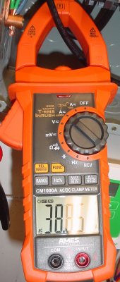
The manufacturer’s LRA spec on the well pump is 41, here is the HF inrush measurement.
I would expect the “41 LRA” spec has some tolerance, so the HF measurement of 38.85A is very good.
well_pump.jpg
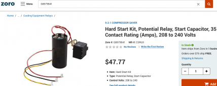
And I now know the effect of the cheap “hard start” kit that i installed on the heat pump in 2017…..it appears to be non-functional at this time………..

5-2-1_compressorsaver_hard_start_kit.png

DSC00211.JPG
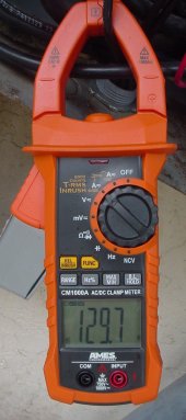
The Copeland scroll compressor on the heat pump LRA spec is 121A.
HF measurement of 129.7A is close enough for government work!

That would explain why the Schneider XW Pro inverter responded “GAKKKKKK” when we did a test starting the heat pump!
 
Let me know what you think of that meter after a few weeks. I may have to get one to add to my kit. My Fluke amp probe has been acting up. May have to send it in for repair/calibration and it does not do inrush directly. But since it outputs a voltage relative to current, hooking to a scope, I get a decent idea, but it is not perfect.

That HAM shack is pretty amazing. How much of that gear is all still functional and actually in use? I do recognize several items.
 
And I now know the effect of the cheap “hard start” kit that i installed on the heat pump in 2017…..it appears to be non-functional at this time………..

View attachment 53596

Considering that these "hard start" units parallel a capacitor with the existing "run" capacitor, I think they would not reduce current. They would actually make a lower impedance connection to the starting winding. What they should do is generate more phase shift, create higher starting torque. Might ramp up faster. Might start when otherwise would stall.

There are apparently self-tuning easy-start kits that learn the motor characteristics and then apply pulses to generate some torque with reduced current draw.
 
Back
Top