diy solar

diy solar

Chargery BMS, DCC (Solid State Contactor) thread.

Yes, wish I would have thought of that. My inverters do not have an on/off switch to turn off with a small relay. They don’t have anyway to communicate with the bms.
As for my charger I wanted to make sure I was cutting off the power the PV panels were providing rather than cutting off the dc from the battery to the charge controller. And also rather than cutting off the charge controller directly while it was charging. I know some charge controllers are fine being cutoff while pv power is going through them but it didn’t seem right to me. Only way to do that is with a relay that can handle the high amperage of my array.
That's the other thing I forgot to mention .... I didn't want to remove battery power from the SCC either. So .... I need one that can be remote turned on and off.
For some people it is contrary thinking .... but it works for me. I think it works for me because I hadn't read very much about it before I started thinking about how to do it. I often don't line up with the status quo.
 
I believe there’s a place for a FET cutoff BMS that both switches the load And signals to other devices that cutoff has occurred, or is about to occur. It would be super helpful if the BMS had “high voltage cell cutoff” and “high voltage pack cutoff” but also “high voltage cell warning” and “high voltage pack warning” which could go to a GPIO and then a user configured microcontroller could use that signal to turn on/off other stuff. just throwin ideas out there
 
I forgot to mention .... I do have a small pack that I just use for electronics in my boat. In that application, the JBD Overkill Solar type BMS is working fine for me. It has very small loads compared to a solar application and will never get too low on a single outing.
 
I have thought about wiring a contactor into the incoming array power negative leads, but then I would need a high voltage dc contactor. or 5 contactors if I didn't want to bond all the negatives. and I'm trying to keep the system as simple as possible.
 
I have thought about wiring a contactor into the incoming array power negative leads, but then I would need a high voltage dc contactor. or 5 contactors if I didn't want to bond all the negatives. and I'm trying to keep the system as simple as possible.
Was simple for my setup. I installed the relay on the pv panel positive that goes into the chargecontroller
 
Last edited:
It should as long as it’s normally open. I also use EV relays. One on the pv panels to stop charging and one on the positive of the battery after the chargecontrollers connection to the battery to stop discharging.
I would instead use the chargery DCC because they use a lot less power than the EV relays
can't use their dcc on my panels 350voc probably don't need them on my dc side as all i'll switch is the inverter power switches.
 
Just be aware that each one of those would draw 1/2 an amp continuously. Depending on how many you have, that could add up to significant parasitic draw.
There are mechanical contactors that have low current draw ..... an can probably be found doing a search on here.

This is why many graduate to a DCC type device that has very low current draw from the 12V.
 
can't use their dcc on my panels 350voc probably don't need them on my dc side as all i'll switch is the inverter power switches.
What’s the max voltage for the chargery DCC?
Then you would want the EV relays. They can handle the volts.
 
What’s the max voltage for the chargery DCC?
Then you would want the EV relays. They can handle the volts.
dcc 100v max. the contactor I linked to above should handle my entire 20kw array, I would have to bond all 5 negatives together, which I don't like, but otherwise I would have to run 5 separate contactors/ssr's
 
dcc 100v max. the contactor I linked to above should handle my entire 20kw array, I would have to bond all 5 negatives together, which I don't like, but otherwise I would have to run 5 separate contactors/ssr's
Don’t all of the negatives come together before the charge controller?
 
How much current will it push? im not using chargery DCCs. Will be using gigavac contactor

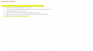
Snapshot from the manual below ...... I have seen posts where the BMS has had problems if higher current relay coils have been used .... and if both charge and load energize at the same time.
I think this can be mitigated by using the external power port.

ChargeryRelays.png
 
How much current will it push? im not using chargery DCCs. Will be using gigavac contactors.
Way back when Craig & myself were testing MANY relays & Contactors, the Gigavac & TE-Kilovac EV200AAANA series Energy savers worked just fine. These do come in different versions so be sure to the Coil Voltage is 9 to 15 volt DC versions. There are Panasonic and other relays which are used in EV's BUT not all are energy savers.

I also had direct dealings with Dongya Manufacturing in China and they also provided equivalent DH200 type Energy Savers at a far lower price of $40USD ea. NOTE THE CODING is not the same. You want a DHV200AAAANH NOTE: H=Horizontal mount (mounts on side of relay) / V=Vertical Mount (mount on the bottom of relay). DATASHEET ATTACHED These can also be 250 or 300A as well.
NB2: NON-POLARIZED !
If a relay is Polarized it means that it is Unidirectional which is only good IF you are running Separate Port Configuration
V stands for non-polarized
200 stands for rated current 200A
The first A: main contact normally open (stud type)
The second A: coil voltage 9V-36V
The third A stands for coil wire length is 390mm
N stands for not with coil terminal connector
H stands for install method is Horizontal
Link to Dongya - REP Emma Chen
OR

They made them up quickly for me and shipped out fast at the time, they also accept PayPal and such without issues.
 

Attachments

  • DHV200 Engery saving datasheet.pdf
    307.8 KB · Views: 1
I do have one concern about using SRRs is that they fail closed (conducting) and since the BMS high/low disconnect is the final "oh crap" line of defense and if the SSR had failed you wouldnt know it until you needed it to disconnect and it didnt happen.

Having said that, 'Quality' SSRs are ultra-reliable and can last decades if not abused. I dunno... the power usage is a non-issue for me since it's dead easy to rig up a Resistor/Capacitor circuit to greatly reduce a contactor coils power usage. I think somebody already mentioned Gigavac - they make awesome contactors and they dont break the bank either.

BTW, you can make a dead simple precharge circuit by jumping the input and output of a relay with a 1.3-1.8 megaohm resistor (depending on system voltage). Its resistance is so high that it won't allow the inverter (or whatever) to turn on but they will keep capacitors mostly charged and it's less than a watt usage.
very interesting. Im looking into getting a bms and this is critical info i had not thought of.
just a thought though, the high Ohms resister jumped across the switch would slowly drain the pack flat if left connected for long periods without charging would it not?
 
Stepping back as it's lost in the thread.
IF the DCC with ISO board is used on the (+) side instead of the (-) side, it sorts the precharge issue and also eliminates some of the flutter seen by the BMS.
 
Way back when Craig & myself were testing MANY relays & Contactors, the Gigavac & TE-Kilovac EV200AAANA series Energy savers worked just fine. These do come in different versions so be sure to the Coil Voltage is 9 to 15 volt DC versions. There are Panasonic and other relays which are used in EV's BUT not all are energy savers...
I was looking at the gigavac gv series which is the kilovac equivalent. Problem is, Jason says the amp rating for the control circuit is 3a. the max needed by the contactor is 3.8. is there some hocus pocus i can do with resistors and capacitors to make it work without stressing the BMS?
 
Back
Top