Firstascent
Solar Enthusiast
- Joined
- Mar 7, 2020
- Messages
- 265
Before you say it, I know there are MUCH cheaper, and easier, ways to do this, and ways to do this without using the Victron Lynx Shunt entirely... but that wouldn't be as fun ") I'm doing this purely because I want to and for aesthetics. So keep that in mind as you read. I'm sure I'm the only one dumb enough to buy a Lynx Shunt to test this out haha.
I'm doing this purely because I want to and for aesthetics. So keep that in mind as you read. I'm sure I'm the only one dumb enough to buy a Lynx Shunt to test this out haha.
I'm using the Batrium BMS, so their Shuntmon is required for proper functionality. I'm also using the Victron Lynx for my DC distribution which led me to want to use the Lynx Shunt for aesthetic reasons. Can't deny the Lynx is a clean setup
Now comes the challenge, how to use both shunts but maintain the clean appearance of the install. Obviously none of this is recommended by neither Victron or Batrium but I'm going for it.
If you're not aware, I don't need two complete shunts, all I need is one shunt but the two separate electronics of each system to function. The Lynx shunt only comes in one option, a 1000A/50mv shunt. The Batrium essentially has two options, a 500A/50mv and a 1000A/50mv shunt, they call the entire shunt package their Shuntmon. In the Batrium software you tell it which shuntmon you have.
Here is the first unknown. Batrium states they do a 10-point calibration to basically "pair" each individual circuit board with each individual shunt for better accuracy. They do have an option where you can send them in a different shunt (ie a 250A shunt or something they don't offer) and they will calibrate your shuntmon for your specific shunt. of course at a cost, and they are in Australia. Without having everything fully connected yet I can't say how accurate it will be connected to a different shunt, but should know in a few days and can compare do some comparisons. Also I should note that I currently have the 500A/50mv shunt but in software I will be telling the Batrium BMS I have a 1000A model and hoping it will calculate accordingly.
Since a shunt is measuring the voltage drop across the "resistor", aka shunt, you need a wire/lead on each side of the shunt to compare. The hole spacing of the Victron Lynx shunt and the Batrium Shuntmon are ALMOST identical! which is a huge plus. This is the next unknown I'll need to work out.
Also, the Lynx Shunt has M5 threads for screws and the holes in the circuit board of the shuntmon where the screws pass through are designed for M4 screws, which means an M5 screw is too big to fit through the holes on the circuit board. yes I checked Quick and dirty option would be drill out the holes in the Shuntmon circuit board just a tiny bit to allow the screw to fit through, but I don't want to do this.
So the current plant is I'm ordering some short aluminum standoffs that have an M5 male thread on one end and an M4 female thread on the other. The M5 male side will also hold down the existing small wire lugs as part of the Lynx shunt and then I'll be able to use M4 screws for the Shuntmon. I should have these standoffs on Tuesday/Wednesday so I can do some further test fitting.
Ok, now comes the last (at least for now) hurdle. The Shuntmon has terminal block connectors soldered on, a 2-pin and a 4-pin each with a 3.5mm pitch. If I place the shuntmon inside the Lynx shunt then it just barely fits WITHOUT the terminals actually connected. So this wouldn't work as-is. What I'll need to do is order and solder in new terminal blocks that have the solder terminals inline with the connector side so that when I plug it in it isn't taking up more space on either side. The photos will really help show what I'm saying here.
I did test fit that I have plenty of internal clearance so I can still fit the Lynx Shunt cover back on over everything with the Shuntmon inside.
That's where I'm at for now. Call me crazy all you want, I'm having fun Constructive Criticism always welcome! I'll keep this updated with further info in the next couple/few days.
Typical Lynx Distribution, nothing custom, no Batrium

Lynx Shunt close-up where the Shuntmon needs to fit

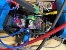
Testing clearance to fit the Shuntmon inside the Lynx Shunt

Shuntmon showing the holes in the circuit board

Shuntmon disassembled

closeup of the Shuntmon circuit board

bottom side of Shuntmon circuit board showing where I'll need to de-solder and re-solder new terminal blocks

The current design of the terminal blocks on the Shuntmon wouldn't allow me to actually plug in the connector. The Lynx case fits right where the black rubber piece is on the busbar.

If I solder on new terminal blocks that allow me to plug in from the top side then I think this would work perfect.

This is simply the Batrium Shuntmon unscrewed from the supplied 500A/50mv shunt.

I'm doing this purely because I want to and for aesthetics. So keep that in mind as you read. I'm sure I'm the only one dumb enough to buy a Lynx Shunt to test this out haha. I'm using the Batrium BMS, so their Shuntmon is required for proper functionality. I'm also using the Victron Lynx for my DC distribution which led me to want to use the Lynx Shunt for aesthetic reasons. Can't deny the Lynx is a clean setup
Now comes the challenge, how to use both shunts but maintain the clean appearance of the install. Obviously none of this is recommended by neither Victron or Batrium but I'm going for it.
If you're not aware, I don't need two complete shunts, all I need is one shunt but the two separate electronics of each system to function. The Lynx shunt only comes in one option, a 1000A/50mv shunt. The Batrium essentially has two options, a 500A/50mv and a 1000A/50mv shunt, they call the entire shunt package their Shuntmon. In the Batrium software you tell it which shuntmon you have.
Here is the first unknown. Batrium states they do a 10-point calibration to basically "pair" each individual circuit board with each individual shunt for better accuracy. They do have an option where you can send them in a different shunt (ie a 250A shunt or something they don't offer) and they will calibrate your shuntmon for your specific shunt. of course at a cost, and they are in Australia. Without having everything fully connected yet I can't say how accurate it will be connected to a different shunt, but should know in a few days and can compare do some comparisons. Also I should note that I currently have the 500A/50mv shunt but in software I will be telling the Batrium BMS I have a 1000A model and hoping it will calculate accordingly.
Since a shunt is measuring the voltage drop across the "resistor", aka shunt, you need a wire/lead on each side of the shunt to compare. The hole spacing of the Victron Lynx shunt and the Batrium Shuntmon are ALMOST identical! which is a huge plus. This is the next unknown I'll need to work out.
Also, the Lynx Shunt has M5 threads for screws and the holes in the circuit board of the shuntmon where the screws pass through are designed for M4 screws, which means an M5 screw is too big to fit through the holes on the circuit board. yes I checked
Quick and dirty option would be drill out the holes in the Shuntmon circuit board just a tiny bit to allow the screw to fit through, but I don't want to do this. So the current plant is I'm ordering some short aluminum standoffs that have an M5 male thread on one end and an M4 female thread on the other. The M5 male side will also hold down the existing small wire lugs as part of the Lynx shunt and then I'll be able to use M4 screws for the Shuntmon. I should have these standoffs on Tuesday/Wednesday so I can do some further test fitting.
Ok, now comes the last (at least for now) hurdle. The Shuntmon has terminal block connectors soldered on, a 2-pin and a 4-pin each with a 3.5mm pitch. If I place the shuntmon inside the Lynx shunt then it just barely fits WITHOUT the terminals actually connected. So this wouldn't work as-is. What I'll need to do is order and solder in new terminal blocks that have the solder terminals inline with the connector side so that when I plug it in it isn't taking up more space on either side. The photos will really help show what I'm saying here.
I did test fit that I have plenty of internal clearance so I can still fit the Lynx Shunt cover back on over everything with the Shuntmon inside.
That's where I'm at for now. Call me crazy all you want, I'm having fun
Constructive Criticism always welcome! I'll keep this updated with further info in the next couple/few days.Typical Lynx Distribution, nothing custom, no Batrium
Lynx Shunt close-up where the Shuntmon needs to fit
Testing clearance to fit the Shuntmon inside the Lynx Shunt
Shuntmon showing the holes in the circuit board
Shuntmon disassembled
closeup of the Shuntmon circuit board
bottom side of Shuntmon circuit board showing where I'll need to de-solder and re-solder new terminal blocks
The current design of the terminal blocks on the Shuntmon wouldn't allow me to actually plug in the connector. The Lynx case fits right where the black rubber piece is on the busbar.
If I solder on new terminal blocks that allow me to plug in from the top side then I think this would work perfect.
This is simply the Batrium Shuntmon unscrewed from the supplied 500A/50mv shunt.
.jpeg")