


You are using an out of date browser. It may not display this or other websites correctly.
You should upgrade or use an alternative browser.
You should upgrade or use an alternative browser.
SOK Troubles (user error)
- Thread starter Sabre36
- Start date


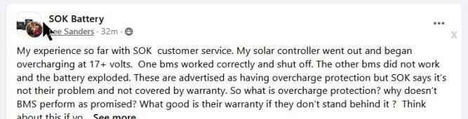
"They sell it as "protected from over charging", guess it's notWould you expect them to stand behind the BMS if you connected the battery directly to a 120vac socket?
"They sell it as "protected from over charging", guess it's not
Most LFP batteries are sold with this expectation. But virtually none of them would protect under this circumstance. I believe your expectations are unreasonable (plug the battery into a wall socket and it will protect itself). Agree to disagree - but this is not unique to SoK.
One of the batteries worked, the other did not..Most LFP batteries are sold with this expectation. But virtually none of them would protect under this circumstance. I believe your expectations are unreasonable (plug the battery into a wall socket and it will protect itself). Agree to disagree - but this is not unique to SoK.
Last edited:
One of the batteries worked as it should have the other did not..
He got lucky with the other battery. Electronic components don't always fail the same way when exposed to high voltage. The battery failed due to overvoltage not overcharge. There is no such thing as "worked the way it should have" when you abuse the battery.
RVLiFe
Solar Enthusiast
- Joined
- Jun 14, 2021
- Messages
- 234
Agreed, this would be for my battery compartment in my 5th wheel. I think a fire under my bedrooms closet floor would be a high risk as well. These things are known to go up pretty quickly.Halon releases a deadly gas when discharged on a fire , would not be good if released in a living environment.
Alkaline
Solar Wizard
Because if the BMS failed, it should have stopped sending power to the cells, I don't understand why people are failing to grasp this concept:Would you expect them to stand behind the BMS if you connected the battery directly to a 120vac socket?
BMS Failure = Battery Disabled
BMS Failure != your cells are gonna turn into a bomb.
What is the point of a BMS if it doesn't disable the battery. Poorly designed BMS.
Same with DALY, poorly designed.
If the BMS had failed, ok fine, SOK should be like Ok pay for a new BMS and swap it out you'll be good.
now instead you have 4 ruined cells and case.
My suggestion to the OP is to not let up, I mean if you wanted no service, you could have gotten a bottom of the barrel priced battery from amazon.
SOK is supposed to be at least mid tier.
Alkaline
Solar Wizard
If you had a JBD BMS, it disables the battery when it detects over voltage, so no power can go to the cells. I think someone needs to be a voltage test on these SOK to see if it really has over voltage protection. 17 volts is not a lot, unless the OP is not telling the facts and the over voltage was way over like 30 volts or something.
AKvalleyguy
Solar Enthusiast
- Joined
- Nov 21, 2021
- Messages
- 142
https://diysolarforum.com/threads/sok-and-furrion.36884/
Interesting coincidence regarding these two threads.
Interesting coincidence regarding these two threads.
We'll have to agree to disagree with those who think that applying 60v to a 12vdc FET-based Battery will reliably disconnect the battery. FETs don't work that way, period. The way FETs tend to fail is to continue passing current. That's why you see so many discussions about FET versus relay/contactor for DIY batteries. Batteries at this price range are not going to handle it as well as higher-priced batteries (which use FETs that can withstand higher voltages, and are better-designed).
The battery was abused. Warranties never cover abuse.
As some of this is a matter of opinion, I'm done beating the horse from my side")
The battery was abused. Warranties never cover abuse.
As some of this is a matter of opinion, I'm done beating the horse from my side
If you had a JBD BMS, it disables the battery when it detects over voltage, so no power can go to the cells. I think someone needs to be a voltage test on these SOK to see if it really has over voltage protection. 17 volts is not a lot, unless the OP is not telling the facts and the over voltage was way over like 30 volts or something.
We can't know the voltage that the BMS was exposed to unless we know the solar panel configuration. All it had to do was spike to 60v for a moment and the BMS would fail closed and then of course the system will read 17v because the cells will pull down the voltage.
mrzed001
Voice of reason
If you had a JBD BMS, it disables the battery when it detects over voltage, so no power can go to the cells. I think someone needs to be a voltage test on these SOK to see if it really has over voltage protection. 17 volts is not a lot, unless the OP is not telling the facts and the over voltage was way over like 30 volts or something.
You can learn how FETs work from this video
EVERY FAT based BMS (for 48V batteries) will die if you put 120-400Vdc on it.
FET burns out to short.
Only relay based BMS can disconnect ... maybe.
And even that is not sure.
If you put 400Vdc on a relay that is designed for 50-60Vdc, its contactors can weld to the contact points.
Or can have a continuous arc melting everything.
TorC
Solar Enthusiast
- Joined
- Jan 13, 2022
- Messages
- 514
@Alkaline As has been explained, every component has a failure threshold above which you get a catastrophic and likely undefined failure. MOSFETs, as used in most low cost BMSs for many good reasons, tend to fail closed. I think at least one 48V BMS has been inspected by @upnorthandpersonal and found to contain 100V rated MOSFETs. That is a reasonable margin, and above that the costs go up substantially. That said, as this potential issue becomes known, I think we'll see more devices showing the maximum fault voltage before damage in their spec.
williamsk913
New Member
- Joined
- Sep 27, 2019
- Messages
- 99
He said 17plus. Which depending on panels (if residential) could be on up over 100v, depending on how many and how they are configured. If the BMS failed, no idea how many volts they were subjected to- I highly suspect that since SOKs can be wired in series that it was much higher than 17v!If you had a JBD BMS, it disables the battery when it detects over voltage, so no power can go to the cells. I think someone needs to be a voltage test on these SOK to see if it really has over voltage protection. 17 volts is not a lot, unless the OP is not telling the facts and the over voltage was way over like 30 volts or something.
Alkaline
Solar Wizard
@Alkaline As has been explained, every component has a failure threshold above which you get a catastrophic and likely undefined failure. MOSFETs, as used in most low cost BMSs for many good reasons, tend to fail closed. I think at least one 48V BMS has been inspected by @upnorthandpersonal and found to contain 100V rated MOSFETs. That is a reasonable margin, and above that the costs go up substantially. That said, as this potential issue becomes known, I think we'll see more devices showing the maximum fault voltage before damage in their spec.
Can we stop with the Bro Science for a minute? I have actually designed electronics, have an engineering background for 25 years in software and 10 years in hardware, I know the MCU that 90% of these BMS units which is either an ATMEGA328P or STM MCU, I know of the shunts they use, the TI and literally all other components. I could literally release my own BMS with a super accurate SOC using a bq769x0 & BQ78350-R1A but could never match the manufacturing costs in China. All these BMS are an Arduino or stm development board and souped up with fets, buss bars that reliey on ADC inputs on the mcu (which is not the best way btw).
This has nothing to with components failing, it has everything to do with what happens when components fail and the default state of those components in a failed state.
If the power supply in your computer fails it should not send 120V ac straight to your motherboard. And if a BMS fails the MCU should disable the unit or the failed components default state should be off. Any BMS that fails and leaves a direct closed circuit is dunce of a design.
Bottom line if a BMS fails, it should stop power going in / out of a battery. If it does not then its not a BMS its a joke, albeit one that burn your house/rv down.
Alkaline
Solar Wizard
Nope it should burn up and no longer allow power to go in our out of the unit. But if burns up and allows power to flow in/out then its a badly designed unit.Does anyone know of a BMS that will reliably disconnect when plugged into a 120Vac socket?
mrzed001
Voice of reason
Nope it should burn up and no longer allow power to go in our out of the unit. But if burns up and allows power to flow in/out then its a badly designed unit.
You know, it can be cheap or it can be reliable.
No third choice.
You could put a big security contactor/relay into the BMS (+FETs).
But it will cost a lot. It has to break 200A and 10-15 kAI.
Also high Amp relays are not very reliable.
Or you can design a crowbar into the BMS that shorts PV + to - ... but it will short battery + to - too and that would be very very VERY bad.
Even if you have a fuse or breaker it comes after the BMS.
So, you have to break it on PV side before the MPPT (high Vdc and low Amp).
And that is not the job for the BMS.
Any other ideas are welcome.
TorC
Solar Enthusiast
- Joined
- Jan 13, 2022
- Messages
- 514
Then can you give any hints as to how to find a BMS that would fail safely? I've been under the impression that low resistance, high power handling solid state components don't have a reliable fail open mode. If you have any suggestions I'm open. Something like a Batrium can use a contactor, which, as just mentioned, has its own problems, including that, while a MOSFET BMS can shut down current unidirectionally, a contactor BMS cannot do that. Being able to do so is a good thing in case of either under or overvoltage - stop the problem while allowing the battery to return to the state it should be in.
If you can design something with a MOSFET level power consumption (≤5-8Wh/day MOSFET loss on a good sized system) and ensure a fail open in this situation, I'd think your price point is more in line with REC or Batrium. I know I'd pay that, but I see them as having their own problems that the cheaper MOSFET BMSs solve, including being a fraction of the idle loss. AFAICT, if it's possible, the reason no one has done this is because the root problem isn't yet widely known, but it soon will be known.
If you can design something with a MOSFET level power consumption (≤5-8Wh/day MOSFET loss on a good sized system) and ensure a fail open in this situation, I'd think your price point is more in line with REC or Batrium. I know I'd pay that, but I see them as having their own problems that the cheaper MOSFET BMSs solve, including being a fraction of the idle loss. AFAICT, if it's possible, the reason no one has done this is because the root problem isn't yet widely known, but it soon will be known.
Similar threads
- Replies
- 6
- Views
- 247
- Replies
- 4
- Views
- 264
- Replies
- 147
- Views
- 7K
- Replies
- 8
- Views
- 470