Hello everyone.
I have a problem that I would like to submit to the forum.
I live on my boat, not in port, and I have this system:
2 x 100w solar panels
1 mppt regulator
1 monitor
1 dc-dc chargher 30A
1 lifepo4 12V 280Ah
1 daly bms 250 Ah
1 inverter 3kw-6Kw.
220v household appliances:
fridge A +
food processor (400W) 15-20 minutes per day
coffee machine (350 W) 15 minutes a day (4 coffees X 2 times usually)
Water heater (1200W) 20 minutes every other day
electric grill (1200W) 20 minutes sometimes
The first time I mounted the system the bms gave 90% charge, and so I charged with the dc-dc charger until I had 100% (display on the charger gave 0A)
I normally used the fridge and the coffee machine and the solar panels managed to guarantee enough current (after 10 days I had 80% charge)
Then I tried to use the water heater, but the voltage drop (up to 10.6 V) causes the inverter to trip (is this normal? Is the discharge too violent?)
Then I had a few days without sun, and the battery went down.
everything ok up to 53%, and I was quiet, then the bms disconnected everything (at night) and we were left in the dark (luckily I have a generator)
As soon as the generator was turned on, the Daly monitor gave 0%.
After 30 minutes (25Ah x 1/2 hour = 12A) everything started again and the bms monitor gave 3%.
In the morning the Daly monitor gave 40%, without having added power, then I charged 2 hours with the generator (25Ah X2 hours = 50A) and the monitor gave 50%.
Now the sun is back, the panels are charging, the Daly monitor gives 60%, but during the night everything is still turned off, and, after turning on the generator, the Daly monitor was giving 1%.
How is it possible that the Daly monitor is unable to measure the real state of charge of the batteries?
The Victron Monitor also gives charged batteries, but unfortunately, below 53% the bms drops and leaves us in the dark.
Does anyone already have similar experiences?
There is a solution ? or just don't go below 53%?
thank you very much for the time you dedicate
Alberto
Your Daly "smart" BMS is unable to report the genuine State-of-Charge (SOC) of a controlled battery. Information displayed on the Victron is generally better. (I have smaller Daly BMS "Smart" BMS than you do, only 200A, and a smaller battery pack - but that battery pack can easily handle continuous loads in excess of 1200 Watts through a 120-VAC inverter.)
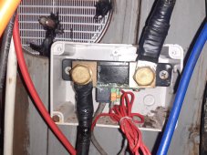
The water heater is a purely resistive load, but runs at full power for a long time. Your 1200W heater unit would require about 1500W input from the battery to the Inverter, if efficiency is about 80%. At roughly 12.8V in well-configured discharge, this is about 120 Amps.
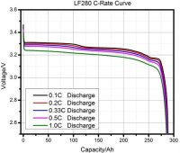
You may note, from the attached graph, that the LFP cells (if EVE, and rated for 1C) have very little voltage drop within the cells themselves (while supporting this current, and with more than 50% SOC remaining). The problem is almost certainly in your wiring:
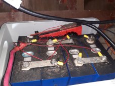
Your 3 Bus Bars, between battery cells, need to be very large. Bus bars which are sent "for free" with battery cells are
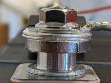
never big enough to handle your needs. You need to either stack multiple little ones (perhaps 4 of them on each bus) or obtain a much bigger one. The second photo shows
my own bus bar assembly, used for my EVE-230Ah cells, with a double pair pressed in to possibly assist the very large "main" bar underneath. The bolts must also be properly tightened, using a small torque wrench.
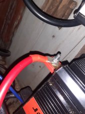
Between the battery pack and the "12V" Inverter connector lugs, you also need some big cables. Pairs of AWG 2/0 on each terminal, or a single AWG 4/0, should be adequate if lengths are not excessive. I don't know the equivalent EU cable sizes, but you can look them up pretty easily.
When the household fridge starts the compressor, there is short term but very high current draw for "compressor start". This is possibly 7x greater than the rated power of the fridge, and may be associated with the specific shutdown events.
- - -
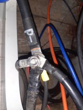
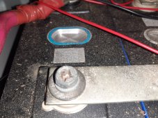
In short, I am inclined to blame bus bars or inverter's "12v" supply wires, as the likely cause of low voltage problems. Can you post a photo for one of your 3 bus bar assemblies, and are you sure that the bus bar terminal nuts have been correctly tightened?