Ampster
Renewable Energy Hobbyist
I presume he used circuit breakers from the 200 Amp panel's bus bar to feed those other devices.What hardware would you recommend to split the 200A feed into 3 outputs?


I presume he used circuit breakers from the 200 Amp panel's bus bar to feed those other devices.What hardware would you recommend to split the 200A feed into 3 outputs?
I presume he used circuit breakers from the 200 Amp panel's bus bar to feed those other devices.
I should have known. I did not look to see whose setup he was asking about. Nice explanation.Not any more.
No battery or solar tied in yet. ....so I'm guessing that this is normal behaviorInverters are power by the batteries ( or solar with some brands ), not the AC lines, so that is likely what you are seeing
I just bought this 2 pole 200A breaker from Lowes for $140 delivered (took 2 days) for exactly this purpose. Looks well made and it's outdoor rated if that's required. I'll be installing it to go between my meter and the SA 15k.Yes I do and already setup with a CLP so a utility disconnect would not be too bad to deal with.
No that feed from the photo is straight from the meter, no breakers in between. Would it be worth the cost to add a 200a breaker between the meter and main? Maybe switch to copper post-breaker?
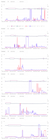
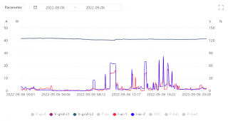
The graphs showed when a device pulled 40+ amps on L1, the voltage on L2 dipped a bit. Hence my suggestion.I also swapped my CTs last night, as @fromport pointed out from the charts they were on the wrong legs.
So unknown devices pulling 40+ amps on either L1 or L2 showed a few volts drop.Did the software fixes also eliminate melted insulation on aluminum wires?
The house is 20 years old and I've only been here for 1, so it could be an issue that was previously remedied. I am not making any assumptions here, still planning on looking into the melted wires.Did the software fixes also eliminate melted insulation on aluminum wires?
Since he sells them, odds seem pretty good he'd focus on them in a future YouTube video or two...I think that's what happened. Like he said, the two battery busbars aren't connected together, so he tried to push about 240A through a single pole of the double pole 200A breaker and popped it.
An impressive demonstration though. Would be interested to see if he reviews the EG4 6500 inverters and tests them out.
 practicalpreppers.com
Yeah, probably will see something on them, he had a couple of them on the wall, so I imagine he'll post something soon. I think he said he's supposed to get one of the new EG-4 LL's and will use it as a master battery with the older batts.Since he sells them, odds seem pretty good he'd focus on them in a future YouTube video or two...
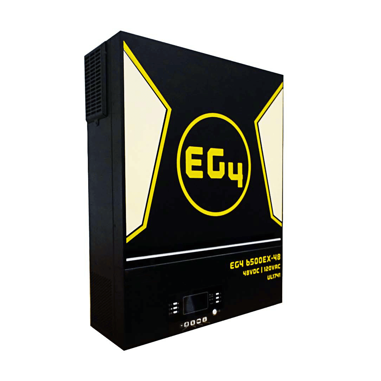
EG4 6.5kW Off-grid Inverter - Practical Preppers
The EG4 6500 EX-48 is a residential self consumption, multi-functional inverter/ charger, combining the capabilities of an inverter, MPPT solar charger, and a battery charger to offer uninterrupted power support in a single package. $1,249.00 Call us at 864-915-1855 or email us at...
I have the same 15k Sol-ark. I checked this morning. There is a bus bar visible under the 200a battery breaker that bridges both poles of the breaker. Thus, they are paralleled on mine.....
Did they remove it on newer builds?View attachment 112297
I think that's what happened. Like he said, the two battery busbars aren't connected together, so he tried to push about 240A through a single pole [connected to a busbar] of [a single]thedouble pole 200A breaker and popped it.