diy solar

diy solar

Building the sickest ® VAWT ever. Brilliant minds unite please!!

I am now printing this.
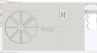
1665954411486.png

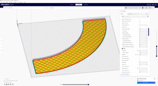
it's not yet with iron filled pla though. It is an attempt to have an iron filled disc that does not buckle towards the magnets.
If this works then we'll have some indication on how much the iron powder will improve on the open circuit power potential of the alternator. If any.

But my best guess is, based on Tesla meter readings done, that it will most likely close to double.

I am far from happy with this model, but I need to plow through now as I have already crossed the 14 day deadline
 
O/k start from basics.
First build a very strong and rigid hub and bearing assembly that you can do some testing with. You may probably already have that.
Bolt two thick very strong steel discs onto that, that run perfectly true, and can be adjusted for the distance apart with one or more removable bolted on spacers.
Fit your magnets around the two inside faces of both the steel discs, so they alternate, north pole up/south pole up around the disc edge.
Arrange it, so the north pole on one disc is facing directly towards the south pole on the other opposing disc.
There will then be a massively strong attractive magnetic force between the two discs, which is why the whole thing needs to be built extremely strong.

Start testing with just one coil. The wire you use must be thick enough to carry the expected final current. How many turns will fit depends on the space available in the air gap between the magnets. Fewer turns mean you can reduce the separation between the rotating magnets and still have a safe clearance. That greatly increases magnetic field strength, but few turns also reduces the voltage. Adding more turns means the discs must be set further apart to clear the fatter winding. Do some testing to work out the best compromise combination.

Fewer turns means less total wire length, and a lower ohmic resistance, which will give better voltage regulation. So don't be in too much of a hurry to keep adding turns making huge coils with excessive turns, unless that shows as a definite advantage of voltage versus rpm.

Do all your testing under full load current, one winding will have only a dissapointingly low voltage all by itself, but it still must be able to produce full expected final current.
After a lot of testing and experimentation, you should have something that will run at full final load current continuously without getting too hot, and you will also by then have a pretty good idea of the voltage generated versus rpm for that one single solitary coil.

If you (for example) plan on 1.2Kw at 60 volts, that will be 20 final dc amps. The current in each leg of a three phase alternator should be designed for 83% of that, or be capable of running continuously at sixteen to seventeen amps. The reasons for that are rather complicated, so don't worry about it.
Just realize that whatever ac current your test coil is happy running at, you will get about roughly 20% more dc current than that when there are three phases feeding into a six diode rectifier. Concentrate first in safely reaching the required current without overheating, don't worry about the final voltage at this stage !
How hot the windings get is difficult to estimate, it depends on how well they can shed heat, so practical testing will be the best way to find out.
As its only one coil you are testing, that should not be too difficult.

Once you know your alternator can run at the required full rated current, its then just a case of completing windings for all three phases.
The only question then is how fast it needs to turn to generate 60 volts dc.
Realize that it can generate ANY required voltage, it just needs to turn fast enough.
Output voltage will be directly proportional to rpm.
Until you have built and tested your wind turbine, there is no way of knowing what sort of step up drive ratio you will need to match the two together.

Forget about direct drive and 60rpm, that is never going to work.
Also forget about metal powder, that is not going to work either.
You say you will never use any type of gearing or speed step up.
That is most unfortunate too.
I wish you luck, but a correct methodical engineering approach to all this is the only way its ever going to be successful.
Fully sick is not going to cut it...
 
Last edited:
O/k start from basics.
First build a very strong and rigid hub and bearing assembly that you can do some testing with. You may probably already have that.
Bolt two thick very strong steel discs onto that, that run perfectly true, and can be adjusted for the distance apart with one or more removable bolted on spacers.
Fit your magnets around the two inside faces of both the steel discs, so they alternate, north pole up/south pole up around the disc edge.
Arrange it, so the north pole on one disc is facing directly towards the south pole on the other opposing disc.
There will then be a massively strong attractive magnetic force between the two discs, which is why the whole thing needs to be built extremely strong.

Start testing with just one coil. The wire you use must be thick enough to carry the expected final current. How many turns will fit depends on the space available in the air gap between the magnets. Fewer turns mean you can reduce the separation between the rotating magnets and still have a safe clearance. That greatly increases magnetic field strength, but few turns also reduces the voltage. Adding more turns means the discs must be set further apart to clear the fatter winding. Do some testing to work out the best compromise combination.

Fewer turns means less total wire length, and a lower ohmic resistance, which will give better voltage regulation. So don't be in too much of a hurry to keep adding turns making huge coils with excessive turns, unless that shows as a definite advantage of voltage versus rpm.

Do all your testing under full load current, one winding will have only a dissapointingly low voltage all by itself, but it still must be able to produce full expected final current.
After a lot of testing and experimentation, you should have something that will run at full final load current continuously without getting too hot, and you will also by then have a pretty good idea of the voltage generated versus rpm for that one single solitary coil.

If you (for example) plan on 1.2Kw at 60 volts, that will be 20 final dc amps. The current in each leg of a three phase alternator should be designed for 83% of that, or be capable of running continuously at sixteen to seventeen amps. The reasons for that are rather complicated, so don't worry about it.
Just realize that whatever ac current your test coil is happy running at, you will get about roughly 20% more dc current than that when there are three phases feeding into a six diode rectifier. Concentrate first in safely reaching the required current without overheating, don't worry about the final voltage at this stage !
How hot the windings get is difficult to estimate, it depends on how well they can shed heat, so practical testing will be the best way to find out.
As its only one coil you are testing, that should not be too difficult.

Once you know your alternator can run at the required full rated current, its then just a case of completing windings for all three phases.
The only question then is how fast it needs to turn to generate 60 volts dc.
Realize that it can generate ANY required voltage, it just needs to turn fast enough.
Output voltage will be directly proportional to rpm.
Until you have built and tested your wind turbine, there is no way of knowing what sort of step up drive ratio you will need to match the two together.

Forget about direct drive and 60rpm, that is never going to work.
Also forget about metal powder, that is not going to work either.
You say you will never use any type of gearing or speed step up.
That is most unfortunate too.
I wish you luck, but a correct methodical engineering approach to all this is the only way its ever going to be successful.
Fully sick is not going to cut it...
Yes sir, You are the first to set me free. Thank you.

I was still torn between small scale tests and full scale tests and opted for leaning as much as I could towards full scale because I have been shouting from rooftops and I did not want to disappoint anyone.
And even that can not get any better than 1/8th of the alternator at a time as I bit off far more than I can swallow.
Sooo many aspects to consider so thank you for real.

I hope my dear readers can revel in the results thus far in that an 80 wind (160 n (turn) ) without iron powder can do around 1.6V at 60 rpm.
Please allow me to explain why I keep saying wind, in the context of coil winding, while others keep saying turn.
That is because a wind, at least how I use it, is a full rotation of wire how I see it. And a turn is just a 180deg. We'll need 2 turns to have a single wind. If I am screwing up here big time please let me know.??????

And I would not be me if I would not foreshadow something amazing. So here goes. I think I have confirmed that a 10mm iron powder disk is likely to double the voltage output. I did so using 2 tests.
1) using my tesla meter to see the difference. And lo and behold and actuall increase of around 100% tesla.
2) a super botched early run of the actual 1/8th disk that showed 30v (that is an increase of 14 volts over the non iron powder test) but there are soo many things wrong with that test that I did not dare to post it yet.

Now I love the fact that you are trying to help and please never stop doing that. However. Did you miss my post in where I pointed out the things that are to my believe sub optimal with your proposal? Now I am not saying mine is better than the standard. I am only saying I have reason to investigate if my train of thought has any merit.

So I will scale things down for the time being. So sorry crew, no car light funerals just yet ;(
I will take your advice with both arms and going single coil testing for the time being.

It will aid in soo many more things, one of them that it is soo much faster to print new ideas while wasting soo much less material for discarded ideas.

And given this law I pointed at a while back, of which the name eludes me right now. The voltage = flux field strength x coil turns x field reversal freq. one.
It really should not matter at what scale I show Sick® results.

But left or right, thank you for trying to keep my feet on the ground.

maximum respect
 
Last edited:
never say never. I am already contemplating that as I slowly began to realize that would make the matching process of the load to the alternator soo much easier if not the only way.

I'll keep one posted.
Its really the only practical way to get started in a project like this.
I know nothing about wind turbines, the guys over at Fieldlines are the acknowledged experts, that is really THE wind Forum.
My area of expertise is in electronics design and electrical engineering.

Treat this as two separate projects to begin with.
Once you have a successful working turbine, and a proven and tested working alternator, coupling both together should be fairly straightforward.
You will then need a wind charge controller, which is an area that even has the Feildlines guys pretty stumped.
 
the guys over at Fieldlines are the acknowledged experts
nah, that is to be taken with a grain of salt when it comes to new comers like me.
I have been trying to get straight answers there as soon someone here early in the thread suggested it.

What I have encountered since then and there there is.
*) my style of communication leads to bans.
*) rather closed style yes or no questions lead to convoluted answers leading even further away from the matter at hand.

I call this wooly science.

If one can't just roll with me and not ban me.
 
I will let you into a little secret about turns, as used in transformers, motors, and generators.
All these devices work on the principle of the interaction of movement between lines of magnetic flux and a straight wire.
One straight wire us usually never enough to do the required job.
So we usually need to use several straight wires physically all arranged in parallel.
For that to work we must connect all our wires electrically in series.

In other words, our single wire passes through the magnetic field, then it must loop back to the starting point and run through the same magnetic field a second time. That requires turns of wire. The bit that loops around outside the magnetic field does nothing, its only the part of the turn cut by the magnetic field that actually does all the work.

The extra wire length just adds electrical resistance. There are two different ways to wind an alternator, with individual coils connected together in series, or with a continuous wave winding. The wave winding uses less wire with less overall electrical resistance. Individual coils might be easier to make and repair, as well as allowing various series/parallel connections for different voltages.

Your observation that winding turns around a magnetic material increases the field strength is perfectly true. Its done all the time in motors and generators. The armature part is never just an air coil, but the windings in the armature always fit into slots in a laminated steel rotor.

For us though, this has one huge disadvantage. Once our coil with its steel (or powdered metal) centre pole piece lines up between two of our very strong magnets, the magnets will not let go.
It effectively locks the rotor and prevents it from turning. That is the well known evil cogging effect.
And it simply will not allow a wind turbine to start up in even fairly strong wind. It can also produce massive vibration.....

So that is why axial flux wind machines always use air cored coils between the magnets. If you disconnect the electrical load, it will spin freely on its bearings and take zero effort to start it turning. Although the large air gap required to clear the coils is a big disadvantage, a wind turbine that cannot start up in light wind is far worse ! So its very strongly recommended that you place nothing magnetic around your wire coils.
 
nah, that is to be taken with a grain of salt when it comes to new comers like me.
I have been trying to get straight answers there as soon someone here early in the thread suggested it.

The Fieldlines guys definitely do know their stuff, but they are not always very good at putting things in simple terms.
Its always difficult to know how to pitch an answer to a question on an internet forum.
Do you treat the questioner as a total novice of low intelligence, or do you reply with just a mathematical formula that only a rocket scientist or nuclear physicist could understand ?

Its also very easy to piss people off.
I understand that your habit of multiple multiple posts one after the other can be really annoying, and it's what got you banned over at the other Forum.

Better to post a decent block of text, rather than using ten separate posts to post ten sentences. We are now at page 52 and NOBODY is going to read right through all that. We should only be at about page ten.

I suggest once you have posted, wait for a reply before posting again. Think about what you want to say, and lay it all down.
The moderators are generally pretty tolerant people, but they do sometimes get annoyed.
 
The Fieldlines guys definitely do know their stuff, but they are not always very good at putting things in simple terms.
Its always difficult to know how to pitch an answer to a question on an internet forum.
Do you treat the questioner as a total novice of low intelligence, or do you reply with just a mathematical formula that only a rocket scientist or nuclear physicist could understand ?

Its also very easy to piss people off.
I understand that your habit of multiple multiple posts one after the other can be really annoying, and it what got you banned over at the other Forum.

Better to post a decent block of text, rather than using ten separate posts to post ten sentences. We are now at page 52 and NOBODY is going to read right through all that. We should only be at about page ten.

I suggest once you have posted, wait for a reply before posting again. Think about what you want to say, and lay it all down.
The moderators are generally pretty tolerant people, but they do sometimes get annoyed.
I'll bring it to the world then. Now when I tried to do it in private to all the moderators on other fora that threatened me with consequences.

I am one of these rare cases of a functional ADHD mind. Now functional does not mean I can simply meld into any kind of community. It means I think and I hopefully did in this one. But in others I need to tip tow my way around things else be banned.

That is just sh*te in my books. I have an IT background I and I am fully aware that the "negative" manifestations of how I operate can be easily dealt with by a simple modification to the code.
This is only relevant of course if the powers that be believe that my input is of value of course.
 
The Fieldlines guys definitely do know their stuff, but they are not always very good at putting things in simple terms.
Its always difficult to know how to pitch an answer to a question on an internet forum.
Do you treat the questioner as a total novice of low intelligence, or do you reply with just a mathematical formula that only a rocket scientist or nuclear physicist could understand ?

Its also very easy to piss people off.
I understand that your habit of multiple multiple posts one after the other can be really annoying, and it's what got you banned over at the other Forum.

Better to post a decent block of text, rather than using ten separate posts to post ten sentences. We are now at page 52 and NOBODY is going to read right through all that. We should only be at about page ten.

I suggest once you have posted, wait for a reply before posting again. Think about what you want to say, and lay it all down.
The moderators are generally pretty tolerant people, but they do sometimes get annoyed.
ok my friend. I am assuming you are the ambassador for me? or for them ;(
Left or right, let's not forget that I have a high commitment to get something on the road that wil benefit all mankind
 
I suggest once you have posted, wait for a reply before posting again. Think about what you want to say, and lay it all down.
The moderators are generally pretty tolerant people, but they do sometimes get annoyed.
this is to the fieldlines yes? I mean here the mods are probably also wondering why I ramble al the time but seem to be less busy with the shutting it down or not.
 
Well.... being part of any community requires a little bit of give and take as well as trying to go with the flow and not piss people off.

I have heard it said that IT people become more used to dealing with "things" than people. I can understand that.
 
I suggest once you have posted, wait for a reply before posting again. Think about what you want to say, and lay it all down.
The moderators are generally pretty tolerant people, but they do sometimes get annoyed.
on other fora I will try and adapt that premise.

Here I feel like this is my diary. And whenever I cross the boundries of this forum I would like to be informed my the mods before I get banned
 
So here I am ok in your books and over else I should me more like you suggested a post above?

Or also here I am leaning towards some boundaries?
And please let's not forget the actual matter at hand. Do you have a response for me about my response on your alternator suggestion?
 
Update.
@Warpspeed I was mistaken. Earlier I said that attracting fields does not double the flux but it actually does.
First when I said that I was quoting some random source online.
But then I went and tested it for my self and I stand corrected.

1666887277770.png
i used the top right print to measure it with my tesla meter. THe little circle in the middle is where the measurement tip went.

in the lower left we can see a test rig that I am printing to test a few variations on magnet arrangements.

I am slowly beginning to believe I have been at this all wrong all the time.

In where it is not about the frequency of magnetic field reversal that is a component in
e = b * l * v
There is no frequency component in that equation.

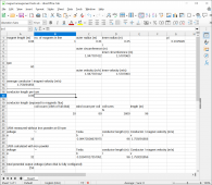
So I am going to take my sweet time to trail and error and see if my spre4adsheet holds up. I think it will give get me close enough

1666894153061.png


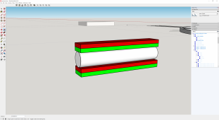
One thing I do not follow yet in theory is why would a coil running through to attracting fields produce any electrical flow?
@Hedges can you take a stab it this? this is basically what @Warpspeed is suggesting to do.

But in my books it will just result in a theoretical 0 flow of electrons.

BTW. the tesla value was goal seeked. As my tesla meter can't be used to measure the value for an area. only for the spot it is placed at.
 
Last edited:
also, placing an iron surface (I used iron powder) behind a magnet will increase the other pole's field strength by around 20%. Not at all interesting if we want to squeeze out all there is to be had.

And another reminder. Stacking these magnets does not double the field strength. More around the 30% mark.

But once again I could be mistaken. My measurement tools could be flawed and/or the way I use them.
 
One thing I do not follow yet in theory is why would a coil running through to attracting fields produce any electrical flow?
@Hedges can you take a stab it this? this is basically what @Warpspeed is suggesting to do.

But in my books it will just result in a theoretical 0 flow of electrons.

Attracting fields, like inside the gap of a horseshoe magnet?
Sure, I'd expect a strong field there, and passing a coil through should get current.

Repelling field like two "N" poles of two magnets held near?
I'd expect a coil run symmetrically between them to get zero net voltage, as some turns see field diverging left to right and some right to left.
In other locations, and especially different orientation and direction of motion, I'd expect something.
 
thank you @Hedges always good to have you on the team.

Please allow me to oversimplify the conundrum.

1666942604558.png

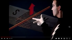
apparently in the context of generators we use the right hand rule in where for motors it would be the left hand rule. A random trivia I picked up along the way I wanted to share with our readers.

Now please consider this

1666942754514.png

I am failing to see why this would not result in 0 electron flow.

Fear not though, I am still working on a physical experiment but since I am actually happy to admit that I am enjoying theory all of a sudden I'd like to debate this theoretically in parallel.
 
Back
Top