diy solar

diy solar

How to correctly install a ACTIVE CELL BALANCER to Lifepo4

Flyfishing55

New Member
Joined
Feb 17, 2020
Messages
38
I have one cell that is running high and my BMS is taking its sweet time balancing so I ordered a 4S active balancer from ebay and when it arrived I installed it similar to how my BMS is installed. It came with no instructions! I put the cables on top of my BMS cables in the same format. I wasn't sure if i should plug in the balancer connector first and then attached the cables to the battery...so I did. Probably a mistake as the wires got hot and so did the balancer. Tried some repair, no luck. Should I have waited to connect the wires to the balancer...at the end? Should I have taken off the BMS wires/cables? Can't find any help on Youtube. Will doesn't show much on his video. Help! thx Tim
 
You may have messed up the balancer but maybe not.

Each balancer I bought has a plug and wires that connect to each cell. I add ring connectors to each wire and solder them even if you are crimp on because I have little trust of crimping wires that small.
Once they cool, I remove the balancer from the wires. Very careful, with a tool that If you drop won't electrically connect between cells and short them. There is usually one wire that is red or black to indicate your starting point. If you have red, black on the ends with white in the middle or different color wires, look at the plug and start with one of the wires furthest to one side. (Normally black or red).
These instructions assume you have a ground, black wire.
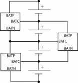
Connect the ground wire to the negative side of the battery. Take the next wire to the ground wire on the plug and connect to the next cell in the pack that would be the + side of the negative terminal. For each wire, continue this until the last wire is connected to the last positive cell that connects to your terminal.

You do not need to remove or disconnect the BMS while you are doing this. Some balancers are sensitive to cells being absent so don't have the balancer board connected while hooking up the wires. Only connect the board to the wire after all terminals are connected and snug.
 
The most serious error would be to have the polarity backwards on any of balancer connections. Second most serious is getting them out of order that may put too much voltage on any single IC in the balancer. Likely to toast balancer either way.

On the ETA3000 chip in the 8 pin package pin 2 should always go to higher positive voltage if you can trace out PCB or ohmmeter check connections. Pin 4 of chip should go to negative most voltage. The chips overlap-leap frog every two sets of cells so for a single chip it spans two cells.

If ETA3000 chip is in the 6 pin SOT23 package pin 2 is battery positive and pin 4 is battery negative.
 

Attachments

  • ETA3000-spec.png
    ETA3000-spec.png
    141.7 KB · Views: 46
  • acitive balancer connections.png
    acitive balancer connections.png
    94.5 KB · Views: 46
Four cell, 280ah, 4S active balancer. I should have never plugged it in until I was done with the terminals... I started with black to main negative (First cell main negative). Next terminal, First cell positive. Second cell positive. Third cell positive. Forth cell main positive. Exactly the same as my 4S BMS. I was hoping my BMS would correct the problem, but that has not happened yet. Current volts this morning: Cell one 3.342/cell two 3.309/cell three 3.482/cell four 3.308. I lowered my bulk and float on my Victron 100/30 to 13.28 and float to 13.13 hoping this would lower my cell 3. I am not using the camper for a couple of weeks. I ordered a new 4S balancer from Ebay this morning. thanks all for your help. tim
 
Each chip moves charge from higher voltage of its two cells to lower voltage cell. It starts up when there is greater then about 0.1v difference between two cells and stops when the two cells get within 0.03v of each other. The overlapping pairing cause the shuffling thoughout the whole series stack of cells.

For a first time setup you should not connect batteries to inverter/charger until they have stablized any voltage imbalance. Remember if two cells are already within the ETA3000 chip's 100 mV activation trip voltage they may not get any additional balancing. Once a chips starts the transfer it will not stop until they are within 30 mV of each other.

So if cells are within 100 mV range the BMS might be okay.
 
I just noticed something that bothers me in ETA3000 spec.

There is a spec called 'Under lock-out voltage threshold', UVLO and it says 3.75v typical. Since these chips were likely originally intended for LiPo type voltage range I hope this UVLO spec doesn't mean they don't do anything if cell is below 3.75v. That would make them pretty much useless for LiFePO4 batteries. If true, maybe they have a version of chip designed for LFP type batteries. Since you are not suppose to be putting a high current rate charging on a very low cell voltage Li-Ion battery having a low threshold voltage limit would make sense.

I'll have to look into this more.
 
Last edited:
The most serious error would be to have the polarity backwards on any of balancer connections. Second most serious is getting them out of order that may put too much voltage on any single IC in the balancer. Likely to toast balancer either way.
The same concept apply to BMS leads. My BMS manufacturer rents a tool to check the connections. I did that the first time but then realized I could sequentially probe the connector and save the $25 and hassle of mailing it back. That BMS is designed for EVs and can handle packs as large as 300-400 volts which would be 100 connections..
 
Does appear to be the case. These cheap ETA3000 active balancers are useless for LiFePO4 cells because they are under 3.75v
 
Under 3.75? Operating voltage is 2.2-4.5. Works on my cells. It doesn’t move power though. Idc what the seller claims, I’ve watched them work and it just bleeds power from the high sell. They are a nice for a backup or to help your bms but I wouldn’t consider them anything more than a backup for your bms.
 
Hmm. That’s interesting. Maybe I didn’t watch long enough or maybe it’s because it’s such a small amount being transferred. If this thing had a smaller trigger than 100mv and more like 50 it would be sweet!
 
I wish they worked for LFP but I am pretty sure they do not. Video looks like all the batteries are LiPo cells which is what balancer chip is designed for. One cell has 3.7v printed on it. There are voltages all over the place from 3.65v to 4.08v. Nothing I would consider soundly in LFP voltage range. Looks like most are very low state of charge LiPo's.

The ETA3000 spec just states Under lock-out voltage as 3.75v 'typical'. No specific low or high range to that. A 3.75v LiPo is at low end of state of charge so not any reason to have balancing below that for LiPo cells.

It is very important that LiPo are not given significant charge rates when cells are below 3.2v to 3.0v. Because the balancing pump can be quite high charge transfer they need to shut down balancer for low voltage cells for safety reasons. Same low voltage charge limitation applies to LFP but below 2.5v.

It might be a relatively simple tweek for the chip design to lower the low voltage cutout trigger limit for LFP voltages with a different version of I.C. I think there would be a good market for them as many power tools are now using LFP to improve safety factor over LiPo. There might begin to be an issue with having enough gate drive voltage for switching FET's in chip at lower voltage.

It is interesting that all the Alibaba and eBay ads are saying they work for LFP and LiPo cells. It would not be the first untrue statement for these sites.

Anyway, I ordered one of the 4s boards that specifically state LFP capabillity which is sufficient for me to test them for the exact voltage their transfer switching shuts down.

The technology approached used is sound, just looks like chips not designed for the lower voltage LFP cells. That low voltage safety requirement is fly in the soup. Too bad they don't have just another pin to select two different low voltage cutout levels.

Will let you know on the results.
 
There might even be the case that they are 'cherry picking' parts for lowest low voltage cutoff.

I still would not be interested in them if they do not maintain transfer switching down to at least 3.3v
 
I wish they worked for LFP but I am pretty sure they do not. Video looks like all the batteries are LiPo cells which is what balancer chip is designed for. One cell has 3.7v printed on it. There are voltages all over the place from 3.65v to 4.08v. Nothing I would consider soundly in LFP voltage range. Looks like most are very low state of charge LiPo's.

The ETA3000 spec just states Under lock-out voltage as 3.75v 'typical'. No specific low or high range to that. A 3.75v LiPo is at low end of state of charge so not any reason to have balancing below that for LiPo cells.

It is very important that LiPo are not given significant charge rates when cells are below 3.2v to 3.0v. Because the balancing pump can be quite high charge transfer they need to shut down balancer for low voltage cells for safety reasons. Same low voltage charge limitation applies to LFP but below 2.5v.

It might be a relatively simple tweek for the chip design to lower the low voltage cutout trigger limit for LFP voltages with a different version of I.C. I think there would be a good market for them as many power tools are now using LFP to improve safety factor over LiPo. There might begin to be an issue with having enough gate drive voltage for switching FET's in chip at lower voltage.

It is interesting that all the Alibaba and eBay ads are saying they work for LFP and LiPo cells. It would not be the first untrue statement for these sites.

Anyway, I ordered one of the 4s boards that specifically state LFP capabillity which is sufficient for me to test them for the exact voltage their transfer switching shuts down.

The technology approached used is sound, just looks like chips not designed for the lower voltage LFP cells. That low voltage safety requirement is fly in the soup. Too bad they don't have just another pin to select two different low voltage cutout levels.

Will let you know on the results.
It absolutely works for lifepo as well.
I wish they worked for LFP but I am pretty sure they do not. Video looks like all the batteries are LiPo cells which is what balancer chip is designed for. One cell has 3.7v printed on it. There are voltages all over the place from 3.65v to 4.08v. Nothing I would consider soundly in LFP voltage range. Looks like most are very low state of charge LiPo's.

The ETA3000 spec just states Under lock-out voltage as 3.75v 'typical'. No specific low or high range to that. A 3.75v LiPo is at low end of state of charge so not any reason to have balancing below that for LiPo cells.

It is very important that LiPo are not given significant charge rates when cells are below 3.2v to 3.0v. Because the balancing pump can be quite high charge transfer they need to shut down balancer for low voltage cells for safety reasons. Same low voltage charge limitation applies to LFP but below 2.5v.

It might be a relatively simple tweek for the chip design to lower the low voltage cutout trigger limit for LFP voltages with a different version of I.C. I think there would be a good market for them as many power tools are now using LFP to improve safety factor over LiPo. There might begin to be an issue with having enough gate drive voltage for switching FET's in chip at lower voltage.

It is interesting that all the Alibaba and eBay ads are saying they work for LFP and LiPo cells. It would not be the first untrue statement for these sites.

Anyway, I ordered one of the 4s boards that specifically state LFP capabillity which is sufficient for me to test them for the exact voltage their transfer switching shuts down.

The technology approached used is sound, just looks like chips not designed for the lower voltage LFP cells. That low voltage safety requirement is fly in the soup. Too bad they don't have just another pin to select two different low voltage cutout levels.

Will let you know on the results.
Operating voltage is 2.2-4.5. It works for both. There is a plethora of information out there with these and life cells. A quick search would have found that.
 
Update,

I received a 4s unit and did a preliminary test. It began to sort of work but quickly broke into what appeared as an oscillatory mode.

I checked it on batteries, supercaps, and controlled power supply for one cell location and selected load resistors on other cell location to control voltage across resistor load to less then 0.15v below power supply voltage on other cell location.

I came across a Youtube video of a British guy that seems to demonstrate a stable operation on supercaps. However he did not measure transfer current and was limited by his supercaps to 2.5v max per cell.

(The 3.75v ULVO, Under lock-out voltage threshold, I was worried about turns out to be minimum sum voltage for both cells in series, not single cell)

The ETA3000 specs has several nebulous items in its spec but one very clearly stated item is in the paragraph titled 'Protection' clearly states if either cell drops below V_precond, which is 2.8v, the transfer current drops to 10% of the level set by ISET pin resistors (ISET = 51K -> 1 amp on received board)

So I tried dropping my 4.2v capable supercaps down to 2.5v volt range and things got stable, just like Youtube video, although transfer current was less then 80 mA measured with a hall effect probe.

It appears that either bad PCB layout or resistance of supplied small gauge connector wires is creating a feedback instablity for higher transfer current.

When I get some time, I will try to remove the conformal coating and change the ISET resistors to set a lower transfer current and see if it operates correctly at normal cell voltages.
 
If the cells were well out of balance there could be too much amperes for the circuit.
 
Each balancer I bought has a plug and wires that connect to each cell. I add ring connectors to each wire and solder them even if you are crimp on because I have little trust of crimping wires that small.

Your mistrust is wise. I have had bad experiences with crimps that have poor connectivity on BMS wire harnesses. From now on I will always crimp then solder.
 
Back
Top