diy solar

diy solar

How to correctly install a ACTIVE CELL BALANCER to Lifepo4

I did notice the wires in above video look several gauges larger then the, about #28, connector wires on unit I just received.

An active balancer has a lot faster feedback loop then dump resistor balancers. I'll have to see if there is a way to ensure this thing remains stable. Even if stable with larger wire, how long can wires be before it becomes unstable again. Length of wires becomes more critical for 16s 48v battery array.

Good idea for higher current balancer but not a solid design in its present construction.

I was really hoping this thing would work.
 

Attachments

  • ETA3000 block diagram.pdf
    433.8 KB · Views: 21
Thought I’d share this but I found that if you pull the insulation off the crimp part, crimp it, then Solder your wire in the crimp valley on top. It’s easy to solder, you can see if t ever comes loose unlike if it’s in the crimp, and at least for me I’m always running out of eyelets so I just unsolder old ones because it’s easy to reuse them that way.
 

Attachments

  • 34BFF5DE-F864-4C53-9D2A-D076E7FF4BC1.jpeg
    34BFF5DE-F864-4C53-9D2A-D076E7FF4BC1.jpeg
    127.5 KB · Views: 15
do you realize that the item showed on ebay is as small circuit probably designed for small 18650 cells, not huge LFP ?
an active balancer is supposed to dump excess voltage form high cells with resistors, so , obviously heating will occur.
but dumping a few milliamp from a 2Ah cell is another story than dumbing Amps form a 100Ah battery.
from specs, the device is able to manage up to 1.5A, that is about 5 Watts.
 
since the device manage cells, if the 1.5A is for each cell, it is 1.5x3.2= 4.8W per cell
but when i see the tiny resistors on the board, i doubt these resistors are able to sustain 5W.
this is a 5W resistor, and if you want to use it at full spec, better to mount it on an heatsink.

1595066985196.png

the device
 

Attachments

  • 1595067193811.png
    1595067193811.png
    611.8 KB · Views: 13
The rare time I go out of balance and this kicks on it puts my 180ah cells back in balance, no problem. When they’re out of balance they’re out in milliamperes In difference, that’s it. If you need to transfer whole amps to put your shit back in balance then you’ve got bigger problems.
 
If the cells were well out of balance there could be too much amperes for the circuit.

The assumption is the board will only produce 1.2a max (1a with the supplied configuration resister) and should not have a problem with too far out of balance.

There are several versions of this board. You can still buy v1 for cheap and there are no safety features that I recall with v1. I am only using v3 or above boards with protection diodes and what seems to be a bug-less (less bugs) board for using LFP batteries.

I too have seen the occolation between the cells with this board. The issue I see is the trigger is 0.1v and the target is much lower. The inverter circuit can not be more than 75-80% efficient. This circuit can only take power from 1 to 2 for one controller. 2 to 3 on another and 3 to 4 for the 3rd controller. Each controller does not know of the others.. In this event, if 4 is low, it takes from 3.. the 2-3 controller sees 3 low and takes from two and the cascade continues unitl each battery looses 15-20% of it's energy trying to balance the pack.

The way I look at this is the purpose of this board is to manage the bank when the cells become more than 0.1v out of balance. There are more expensive methods of active balancing that are much more active and much more accurate.. (Capacitive balancing using FETs) that is very simple, does not use inverters so efficiency is much higher).. I will be building one when I have time with spare parts because I really like that idea but in reality with LiFePo4 just might be overkill since they really don't need that active blancing.. If they do, this board to me is the best of both worlds.. It is not fully active until the battery is near charge (top) or near bottom.. The capactive active balancer I mentioned is active all the time using a flipflop circuit that charges a capacitor so if they are all balanced, no energy is used or transfered except for the bias drain which if done correctectly can be minimized.

Long story short (I know too late), this board in no way is perfect for keeping your cells perfectly balanced. However, for that 6 month balance task you had, you won't anymore after adding this little board.
 
Screenshot_20200718-112027.png
This is my worst ShunBin battery using the little active balancer that Will reported on. This is so much better than before, no more monthly full charge required to keep this 400ah used POS balanced. Use the highest version board you can find, not v2 or under, they were flakey for me.
 
In Will's video, it seems as if he is expecting full current from this board. I tested this theory by using an external, isolated l bench power supply to charge the individual cells. My tests indicated that if the cells are only 0.1 apart, you will not get a charge over 1 amp. If it is bottom triggered, possibly. A 3.2v cell, charging based on a differencial and the target voltage = neighboring cell means I have a cell that is at 3.3v and a cell that is at 3.4v. applying power at 3.4v to the 3.3v cell draws maybe 100ma. Buying a 5amp balancer for this condition will not yield faster results. Your charge between cells 1 and 2 will only be 100ma unless you deliberately increase charge voltage.
 
I use the same basic scheme presently on my system but it works open loop just serially sequencing through the stack relying on the principle the energy from charged coil will be absorbed by the lower of the two cells. No voltage or current sensing necessary. It works well but does waste some time and slight amount of energy when charging coil from lower cells and just returning the charge to same cell.

On this board the voltage comparitor and enable / disable transfer detection creates potential for a lot of feedback problems. I think it may be close to impossible to maintain stability over the near infinite possible load impedances it could see from all cell types, sizes, and wire lengths. It is obvious they somewhat recognized this with the 'ramp down' cycle after each threshold trigger to reduce the effects of positive feedback.

One thing that first concerned me is the stacked IC's run asychronously to one another so depending on cell voltage situation you can have two adjacent IC's pulling and pushing, pushing and pushing, or pulling and pulling on same cell with random amount of time overlapping. This just exacerbates feedback problems.

It would have a reasonable chance if there was odd/even IC synchronization to prevent overlapping charge/discharge and sensing was taken through separate wires directly to battery terminals but that would add more pins to IC and require twice as many interconnect wires.

Easiest thing to do is increasing wire gauge and change ISET resistor to lower transfer current somewhat. If it can be made stable with 0.5 to 0.75 amp transfer then it is of some value, however, not too many folks would be interested in changing chip resistor values on board.
 
It is true that most of the cheap balancers and BMS units just use a small resistor load to pull down the cells that have too high of a voltage, but there are now some decent true active balancers on the market. I looked at all kinds of units before I decided on one. I have about $2,000 invested in the cells so far (Than you Battery Hookup for an amazing deal), and I want to get the most out of them. Keeping them safe is a top priority.

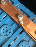
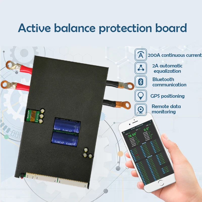
What I ended up using is one of the Ji Kong "JKBMS" balance units. So far it works very well. This system uses a bank of FET's to choose the cell, and a bidirectional switching voltage converter to pull current from the highest voltage cell and store it in a super capacitor. And then it pushes the current from the super capacitor to the lowest voltage cell. It will work at any voltage between 1 and 5 volts.

Here is the one I got for my 14S 6P bank using LG Chevy Bolt cells for a total of 360 amp hours, or about 18 KWH.

I have no connection with these, other than I bought one and it seems to be working great so far. There are several vendors on Ali carrying the same board.

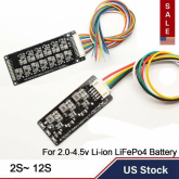
All of the settings are adjustable. They can be used down to just 4 cells, but you will then need to supply 40 volts or so to power the board. Anything over 40 volts and it can just use the power from the pack. The cell difference can be as little as 0.003 volts, and it will still pull and push 2 amps. If you hunt around, they do have this same technology as just a balancer without the protection section. The BMS with the protection shut down is newer. I have only pulled about 15 amps through it so far, so I can't say how well it works under a heavy load yet, but it does balance up my pack very quickly. I ran a 12 volt inverter off of just 4 cells and pulled them down about 0.2 volts below the other 10 cells. In under an hour they were all back within 0.003 volts. The threshold for balancing can be set as well through the iPhone app. I put my down to 0.003 just to watch it work. It shows you which cell it is acting on and how much current it pulls or pushes. They have boards that do .6 amp, 1 amp, and I got the 2 amp. The balance current can also be adjusted down if you don't want to push around 2 amp through thin balance wires. It even measures the resistance of the balance leads and uses that to compensate the voltage as it is pulling and pushing current. I saw this as it was balancing, it chose the highest voltage cell, but one it started to pull 2 amps, the 0.131 ohms of balance lead caused the measured voltage to fall a few millivolts, but it still kept pulling from that cell for a bit before it moved to another high cell. Then it pushed power, cycling across the 4 low cells. If it did not compensate for the wire resistance, 2 amps at 0.13 ohms would make the voltage reading change by about 260 mv, it only changed 2 mv on the status display. For balancer only units, they now have a 5 amp and 10 amp version, but they are a bit more expensive. Mine has 2 35 Farad caps, the 5 amp one has 3 150 Farad caps.
 
Well, I have had the ACTIVE CELL BALANCER on for better part of three days. I lowered the bulk and float hoping to get around 2.5 volts, but no luck. A 4 pack 280 amh battery is just amazing. I ran a double LED light and ran the 2 way frig with the door opened all night and never hit below 3.13 volts. So with all the above info indicating it may be best to balance either at a high or low voltage, I am now shooting for around 3.6 V bulk. Regardless, having a lack knowledge about solar: I am not sure if the numbers I have my on my Xiaoxiang BMS actually indicate that I am balanced (ie MV?). The numbers seem to change throughout the day. I will get some numbers to share tomorrow. Also, how many days should it take for the Active Cell Balancer to complete the process?? I have read every comment and tried to make sense of those. Many of you are truely experts and I appreciate the education. Some of comments are far over my head. Nonetheless, thanks. Tim
 
Do not develope a bad opinion of all active balances based on a few bad designed models.

There are many different active balancing methods out there. The two most prevalent DIY units, that work, are single DC to DC converter based and capacitor charge pump based. They are not the only ways to do it.

Of the present two prevalent types, the single DC to DC converter is probably better although it is very slow in cases where there is wide diversity of cell voltages because it only services one pair of cells at a time, always taking from highest voltage cell and giving to lowest voltage cell. It moves on to the next highest and lowest cells. It can make several passes on all cells as the situation of highest to lowest cell continuously changes due to the progression of balancing. I am a little concerned how the algorithm reacts to outside charge and discharging dynamics. All cells' voltage readings needs to be taken at same instant in time to ensure little influence from external charge or discharge currents through cells. I am not sure the unit is doing this.

Capacitor charge pump works good but long term reliability of all the electrolytic caps, especially when perpentually heated by BMS series MOSFET switch, is questionable.

The single DC to DC converter model also has two large electrolytic caps in the DC to DC converter which is not good for long term reliability.

Resistor dump balancers provide small amount of current balancing and are really only providing for cell self leakage difference compensation. As cells age, their capacity will be reduced and reduced at divergent amounts. At some point it will be very desireable to transfer larger current efficiently between stronger and weaker capacity cells to get the most from an aging array of cells. It also needs to do this across the cell voltage range, not just at the top end state of charge.

Fortunately, this can be added on in parallel to original BMS, later in battery's life cycle. If using used cells, with unknown history, an active balancer makes a lot of sense.
 
Last edited:
With all the batteries people have ballooning out, I really think the bigger balancer you have the better and active is even better.

I inserted one cell into my pack and had it to with in 0.001 volts of the others and it over charged and expanded.....(no BMS at the time but all the cells were very close.)
 
I inserted one cell into my pack and had it to with in 0.001 volts of the others and it over charged and expanded.....(no BMS at the time but all the cells were very close.
If it was within 1 millivolt of the others at the flat part of the curve that was no prediction about where it might be at the upper knee. As far as I know balancers do not cut off charging if a cell starts to run. The first line of defense should always be a BMS.
 
A resistor dump BMS will not save you if you just match voltage at mid state of charge. It is too inaccurate an indicator of SOC and likely cells' voltage would have diverged if cells were left to rest unloaded for a while. Only full charge voltage, dropping to near zero charge current, will assure same (100%) state of charge.
 
A resistor dump BMS will not save you if you just match voltage at mid state of charge. It is too inaccurate an indicator of SOC and likely cells' voltage would have diverged if cells were left to rest unloaded for a while. Only full charge voltage, dropping to near zero charge current, will assure same (100%) state of charge.
I agree with what you are saying about the voltage inaccuracy but a true BMS if configure properly should cut off charging if one cell goes above the limit. AFAIK my Orion Jr BMS is a resistor dump BMS if that is the same as a current shunt?
 
I agree with what you are saying about the voltage inaccuracy but a true BMS if configure properly should cut off charging if one cell goes above the limit. AFAIK my Orion Jr BMS is a resistor dump BMS if that is the same as a current shunt?

I don't agree completely. The new BMS's go up to 5 amps are easy to find. If your first charge and/or discharge is under the BMS current rating it should have a chance of balancing out what is needed to not ruin a cell. Mine were so close I can't believe it happened, it was within a thousandth of a volt. Charge very slow your first couple times for your best luck at balancing the bank.
 
Back
Top