My LG Chem pack is still basically new, and the cells are proving to be very well matched as well as balanced now. This is great for me, but it is not asking too much from my JK BMS balance function. I now have about 20 cycles from about 90% down to 40% and back up again. My pack just started charging this morning, I connected to the BMS and took a screen shot just now.

The cell balance is at 0.006 from the lowest to highest cell. And you can see at the bottom it shows the highest cell in red and the lowest in blue. All the rest are green. I would have to scroll down to show all 14 in my pack. The Cycle count number seemed low, as I know I have more like 20 cycles, but the first few were only down to 60%, the 50% and the last few down just under 40%. I have discharged a total of 2634.6 amp hours out of the pack. The pack is rated at 360 amp hours, and if you divide that, it rounds off to 7 times the pack capacity rating. Now the cycle count makes sense. In the 3 weeks I have had the pack operating, and almost 2 at fairly high power, I have not seen it have to run any balance current with the threshold value set to 0.008 volts differential. It will allow it to be set down to 0.003, but then it is shuffling power around for really no reason. It even lists that the cell measuring accuracy is only guaranteed to within 0.005 volts, so it is pointless to try and balance any closer than that.
Do you need more than 2 amps of balance current?
To give the balancer section a work out, I connected my 12 volt inverter to just 4 cells in the middle of the pack. It was at 60% charge, so it was just below the high volt shut off point. I put about 200 watts of load on it and had it drag them down about 0.060 volts from the rest of the pack, and yes, I had the balancer turned off to make sure it would move. That comes out to a 16 amp load, so the balancer would not have been able to stop the drift, but it would slow it down a bit. It still took a while to get that 60 mv difference. I took the load off and turned on the balancer. I watched the cell voltages page and it was pretty cool to watch the red high cell mark jump around to all of the 10 cells that were higher, and then jump across the 4 that were lower. It kept repeating up and back. The balance current flipping from -1.98 amps to +2.04 amps etc. I saw a high spike of about 2.2 amps and it would dip down to 1.5 at times as it selected a different cell. I did not get an accurate time on it, but in a couple hours, I looked back, and the balancer was turning off and just popping on for a minute once in a while, with the 4 low ones right at 0.008 below the other 10. I set the threshold down to 0.003 and it went back to work pulling them closer still. For my 360 amp hour pack, I would say the 2 amps one cell at a time is plenty of balance current.
Look at it like this... How far out of balance and match do you think your cells are? If you run a capacity test on all of your cells, and let's say the worst high to low was 90 AH to 105 AH and the rest are all close to 100 AH. When the pack charges up, the 90 AH will top out first, and the 105 will be behind the rest. That 105 cell is only at 86% and all the 100's are at 90% when the 90 cell is topped out, and this is from all 16 cells being at 0% to begin. That 2 amps of balance current will take about 5 hours to pull 10 amp hours off of the 90 AH cell, and 2.5 hours to push 5 amp hours into the 105 cell. And you do need to add those times, and double it because it pulls 2 amps, then pushes 2 amps, but in this case there will be a lot of overlap as it will use energy from the 90 AH cell, pulling it's voltage down to then push that to the 105 cell to pull it's voltage up. So it might take 7 hours or so to fully balance a pack that has cells that far out of match. Does the pack charge or discharge faster than that? If it does, you should probably have better matched cells. If your pack has multiple cells in parallel, you should put together groups that help match the capacity of each cell group. If this example was a 16S 3P setup, you should put the 90 and 105 cells in the same group so the high and the low help bring them to the average capacity. 90+100+105= 295 where a perfect group would be 300. That is only a 1.7% low group. Where the 90 out of 100 was 10% low.
If the cell groups are all well matched, it only takes a small balance current to get the cells to get in line in a day or so. And if they are well matched, it will stay in balance with very little current. Mis-matched cell groups will always go out of balance and need more balance current to pull them back in balance. A powerful balancer is kind of like a band aid for a bleeding battery pack. As a pack get's larger, yes, it will need more balance current. So if you are slapping together a 1,000 amp hour bank, you may need 10 amps of balance current. That is just 1% of capacity, so if a cell group is 1% off on capacity, it will be able to keep it balanced during charge and discharge. But if a cell is 2% out, it will take longer to pull it back in balance after charge or discharge has stopped. My 2 amps of balance current is only 0.56% of battery capacity, and it is having no problem keeping them balanced as it appears my cell groups are matched even closer than 0.5%. And yes, you could always just add another balancer unit in parallel if you find you need more current. My original plan was a low current passive balance and an active balancer in parallel, but when I found this BMS with 2 amp active balance built it, it fit my needs quite well. If it turned out I needed more current, I could still add another, but my pack clearly does not need it. I got very lucky with the Battery Hookup deal. I am using each half of an 8S module in series with 2 different complete 10S modules. I could have easilly had cell groups that were not well matched, but I didn't. If I did find a drift issues, I have the 2 10S units starting at the negative end, and the 4S halves at the positive end. That was the easiest to wire, but if I had a match issue, I was prepared to move one of the 4S halves to be at the negative end or even swap the 10S pair so that the full 14S strings would match up, but my first setup is working great. Always keep a close watch on a new pack for several cycles to be sure they are holding a good balance, and of course, don't push the high and low voltage ends until you know the pack is behaving well. I learned a lot working with much smaller E-Bike batteries. messing up with 10-20 AH can still make smoke and fire, but the same issue with 360 AH could burn down a house pretty fast.


 www.aliexpress.com
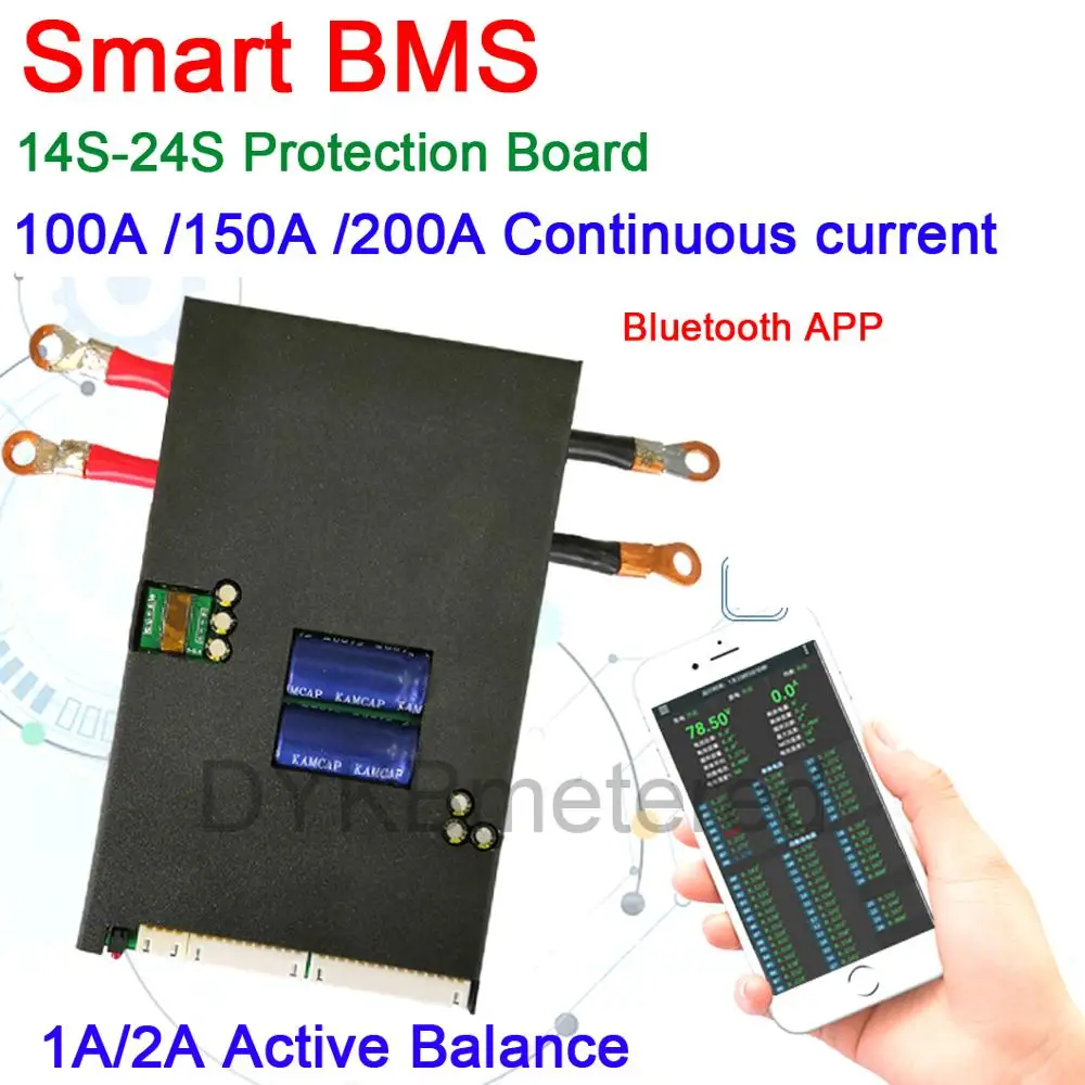
The only little issue may be that it needs 40 volts to operate. It will work with smaller packs, but under 40 volts requires a power source other than the main pack. Some use a small boost converter to make 48 volts to power it up. The bluetooth range is about 30 feet if you can see it, but it does not like going through walls.
www.aliexpress.com
The only little issue may be that it needs 40 volts to operate. It will work with smaller packs, but under 40 volts requires a power source other than the main pack. Some use a small boost converter to make 48 volts to power it up. The bluetooth range is about 30 feet if you can see it, but it does not like going through walls.


