These circuits can be controlled and used in many applications, On when grid is present, On when above a certain State of Charge, On all the time, etc So yes they can be used during self consumption as wellAwesome! Can the loads on these circuits be powered by the inverter when the inverter is operating in grid tie zero export/self consumption mode? Or are those circuits only powered offgrid
You are using an out of date browser. It may not display this or other websites correctly.
You should upgrade or use an alternative browser.
You should upgrade or use an alternative browser.
Midnite Solar Announced their new 10kw AIO at Intersolar Today
- Thread starter HighTechLab
- Start date
Robin Gudgel
MidNite Solar
- Joined
- Aug 23, 2020
- Messages
- 53
Well, I still haven’t figured out how to add the MidNite Solar to my name?
I see some people are interested in using an autoformer from a Schneider or other inverter for a 120/240V autoformer. Make sure you check the voltages before connecting any loads. I believe these magnetics also step up the voltage from battery to something high enough to create the 130v sine waves. So the turns ratio may not be correct. I sort of remember working on the Trace Engineering autoformer back in 1990 or so. It had four identical windings of 10awg magnet wire. 110 turns for each winding. It had 20 pounds of M6 laminations(2.125”). That was only good for 3000 watts continuous without air cooling. So, with the windings, it weighed about 30 pounds. A toroid would be a little more efficient. You may be able to unwind an inverter toroid also? This is all just for a reference for the DIY guys that have parts available to play with, you may be able to get a factory built toroid autoformer off eBay for a decent price too. We used to build the SMA autoformer until they clised down the plant in Poland. That was a great 6000 watt autoformer.
If I can be of assistance with anything, feel free to email me.
Thanks,
Robin Gudgel
MidNite Solar
Robin Gudgel
MidNite Solar
- Joined
- Aug 23, 2020
- Messages
- 53
Well, if you live as long as me and continue designing stuff, you get to be called a Solar Pioneer or something like that. I’m actually on a cruise in the Caribbean at the moment. I would rather be doing this instead of what my wife has in store for me. Going to the gym isn’t my thing!"Solar Enthusiast" is a bit of an understatement.
timselectric
If I can do it, you can do it.
- Joined
- Feb 5, 2022
- Messages
- 18,664
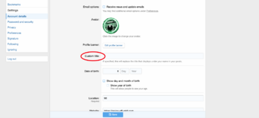
Click on yourself at the top of the page.Well, I still haven’t figured out how to add the MidNite Solar to my name?
Select "account details".
Add "custom title".
Robin Gudgel
MidNite Solar
- Joined
- Aug 23, 2020
- Messages
- 53
Could not find anything called account details.
Adam De Lay
Solar Wizard
I am planning to just use the "high side" of the transformer (120/240 set of windings) with the low side windings just capped off. That way I should be able to input 120V from a small portable generator and bump it to 120/240V split phase. I know, I know, those ones with wheels and handles cause all kinds of service phone calls!I see some people are interested in using an autoformer from a Schneider or other inverter for a 120/240V autoformer. Make sure you check the voltages before connecting any loads. I believe these magnetics also step up the voltage from battery to something high enough to create the 130v sine waves. So the turns ratio may not be correct.
In regards to the ONE, something that may be of interest to others is whether a battery will be needed, or if someone could start out in just a grid-sell setup and add their battery backup later. I believe you had said this was probably going to be do-able. Is that still looking to be possible? I'm sure there are others on here who this would be of interest to.
Also, I will 100% second your thoughts, Robin, on 200A transfer not being cheaper on the install! Something for everyone to keep in mind is that you should ALWAYS have a backup option. While many of us have absolutely great faith in a product by Midnite solar, we all know that any electronic piece of equipment can fail! Therefore you not only need a 200A "visible lockable" disconnect (NEC code). But also some way to bypass that inverter and get grid or gen power to your main panel! Remember, the integrated transfer switch is wholly dependent on being controlled by the inverter, so if the inverter is in an error state, it will likely not give you grid power passthrough either! That normally means either a 200A DPDT transfer switch $$$$$$$!!!, or you can do a sliding main to bus interlock, but generally that limits you to about 125A bus breaker for backup.
Along with the whole bypass, you will now need a second service disconnect, as you run into a very interesting scenario since the 200A disconnect is your PV disconnect. Now you need a separate 100-200A fused disconnect for your bypass!
Don't overlook the fact that I said fused! Both the 200A AND the 100-200A for bypass need to be fused as those are now your service disconnects! And you will need to revise existing grounding, as your bond will now be in the new service disconnect(s). Oh yes, that also means you need to separate out ground and neutral in the main panel..... more time/money! (Many main breaker panels have ground and neutral all run together on the same bars, and it takes a bit of time and effort to separate those out!)
BTW: you need to also fill out the other information that is required on the Account page before pushing the save button.Click on your name on the top right of the screen. Then click Account Details. On the right-hand side, you'll see "Custom Title".
ET: It is possible that a certain post count is required to set Custom Title. That would require action from a Forum Mod or Admin if this is the case.
Last edited:
Robin Gudgel
MidNite Solar
- Joined
- Aug 23, 2020
- Messages
- 53
Well, I probably haven’t posted enough? I can’t get to the screen that allows editing.BTW: you need to also fill out the other information that is required on the Account page before pushing the save button.
ET: It is possible that a certain post count is required to set Custom Title. That would require action from a Forum Mod or Admin if this is the case.
I put in a Report on your post so it can be attended to hopefully.Well, I probably haven’t posted enough? I can’t get to the screen that allows editing.
I did it for you.Well, I probably haven’t posted enough? I can’t get to the screen that allows editing.
Robin Gudgel
MidNite Solar
- Joined
- Aug 23, 2020
- Messages
- 53
Cmiller from Ohio, you definitely see the issues associated with a 200 amp inverter. Give us enough time and we will attempt to solve these issues in an AIO inverter, but physical room becomes the issue. I don’t give up easily though. I have included AC bypass breakers and switches in every prewired system designed since 1993 with the Trace SW and DR units. I want to figure out how this can be done here also, It would really be nice to include some programmable breakers like on the ONE too in order to drop off your hot tub and such when the utility goes out. Like I said, space is the problem. You can always buy one of the new programmable distribution panels, but they cost thousands of dollars. I just cant do that to all of you!I am planning to just use the "high side" of the transformer (120/240 set of windings) with the low side windings just capped off. That way I should be able to input 120V from a small portable generator and bump it to 120/240V split phase. I know, I know, those ones with wheels and handles cause all kinds of service phone calls!But this is for myself, not for a customer. Lol. This is only for when my standby gen takes a dump on me.
In regards to the ONE, something that may be of interest to others is whether a battery will be needed, or if someone could start out in just a grid-sell setup and add their battery backup later. I believe you had said this was probably going to be do-able. Is that still looking to be possible? I'm sure there are others on here who this would be of interest to.
Also, I will 100% second your thoughts, Robin, on 200A transfer not being cheaper on the install! Something for everyone to keep in mind is that you should ALWAYS have a backup option. While many of us have absolutely great faith in a product by Midnite solar, we all know that any electronic piece of equipment can fail! Therefore you not only need a 200A "visible lockable" disconnect (NEC code). But also some way to bypass that inverter and get grid or gen power to your main panel! Remember, the integrated transfer switch is wholly dependent on being controlled by the inverter, so if the inverter is in an error state, it will likely not give you grid power passthrough either! That normally means either a 200A DPDT transfer switch $$$$$$$!!!, or you can do a sliding main to bus interlock, but generally that limits you to about 125A bus breaker for backup.
Along with the whole bypass, you will now need a second service disconnect, as you run into a very interesting scenario since the 200A disconnect is your PV disconnect. Now you need a separate 100-200A fused disconnect for your bypass!
Don't overlook the fact that I said fused! Both the 200A AND the 100-200A for bypass need to be fused as those are now your service disconnects! And you will need to revise existing grounding, as your bond will now be in the new service disconnect(s). Oh yes, that also means you need to separate out ground and neutral in the main panel..... more time/money! (Many main breaker panels have ground and neutral all run together on the same bars, and it takes a bit of time and effort to separate those out!)
And good luck on that autoformer project. We all are curious if it will work.
Thanks,
Robin Gudgel
MidNite Solar
Robin Gudgel
MidNite Solar
- Joined
- Aug 23, 2020
- Messages
- 53
Thank you, thank you, thank you.I did it for you.
Awesome!! Having bypass built-in would be absolutely great!Cmiller from Ohio, you definitely see the issues associated with a 200 amp inverter. Give us enough time and we will attempt to solve these issues in an AIO inverter, but physical room becomes the issue. I don’t give up easily though.
Hedges
I See Electromagnetic Fields!
- Joined
- Mar 28, 2020
- Messages
- 20,739
It would really be nice to include some programmable breakers like on the ONE too in order to drop off your hot tub and such when the utility goes out. Like I said, space is the problem. You can always buy one of the new programmable distribution panels, but they cost thousands of dollars. I just cant do that to all of you!
You have access to SoC, temperature, etc. and know how close to limits your inverter is running. Not all that info is readily available outside.
There are commercially available controllable plugs (quality may be a question.)
A control module like a power relay (signal relay for anything with thermostat) and maybe current sensor, that could be commanded over twisted pair or powerline, would allow implementation without consuming volume in the inverter.
Rather than mucking with firmware inside the inverter, might be better to have an external "programmable thermostat" that just gets vitals from inverter, and that external gizmo could have flow chart, priority table, ladder logic or whatever for user to program.
The ECU in a car shouldn't implement infotainment or climate control system. Just be able to cut out A/C if overheating.
Another thing that would be great is having the ability to integrate with some third party programs such as Home Assistant. Something like that would then open up integration with all kinds of smart switches and smart devices, e.g. smart window A/C unit, smart plug with electric heater plugged in etc., etc. Then the owner (and tinkerer 
 ) of the system would have access to all the internal data such as battery SOC and be able to remotely control things based on excess power or low power.
OffGridForGood
Catch, make or grow everything you can.
...and Solar Assistant (please!)ability to integrate with some third party programs such as Home Assistant.
zanydroid
Solar Wizard
Any info on plans for UL9540 with this inverter?
Either with UL9540 DC ESS or as a paired AC ESS listing.
Either with UL9540 DC ESS or as a paired AC ESS listing.
Brucey
Solar Wizard
Brucey
Solar Wizard
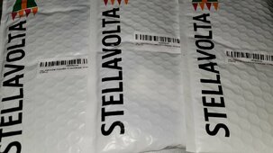
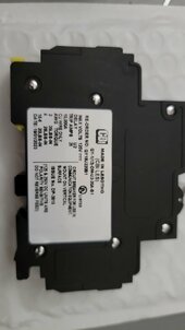
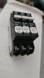
Mnpv6 combiner box should be here Friday.
Similar threads
- Replies
- 3
- Views
- 283
- Replies
- 5
- Views
- 634
- Replies
- 4
- Views
- 529


